In 1995, I signed up with an e-mail forwarding service called pobox.com. They would give you e-mail aliases that would then forward to whatever real e-mail account you were using at the time. The basic plan came with three aliases, and at one point I was using six. Super convienient!
They also added the ability to use those aliases to redirect to a webpage. Back then, your web address might be something long like www.geocities.com/SiliconValley/1842 (my original home page at GeoPages) or be something with a “~” in it like http://www.mcs.net/~werner/yester.html (the original location of www.yesterland.com before it had a domain). Pobox allows aliasing those so users only had to know www.pobox.com/~disneyparks and it would redirect to whatever service I was using to host my theme park photos at the time. Super convenient!
Over the years, my e-mail has moved from service to service to service, yet I never had to change any e-mail addresses with any services, or notify any of my contacts about a new address. They just used the same e-mail address I had since 1995. Super convenient!
The way they handle spam filtering is much worse (no e-mail summary, no one-click way to look at items in a web page and release/white list them, etc.). E-mails from my Softaculus (WordPress) service ALWAYS get spam filtered and they have been unable to fix this. E-mails I send to folks bounce back at the Fastmail level due to reasons I haven’t figured out. It’s a mess.
So, while I told everyone about how great POBOX.COM was for 30 years… I cannot recommend FASTMAIL.COM
But they own the e-mail I have had since 1995 so I guess I am sticking with them. At least for now…
Though, when I bought it, it was significantly cheaper than today’s price.
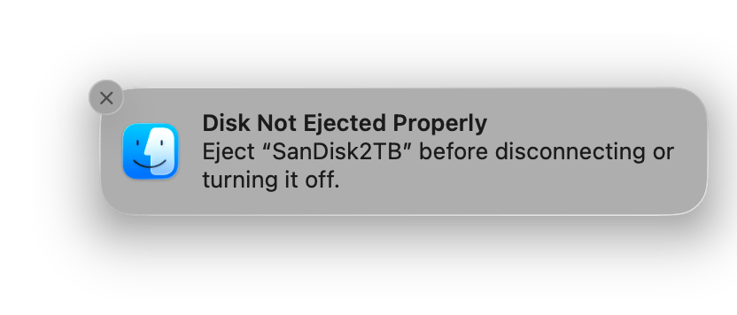
For “some time now” (many months) I have been seeing this popup on my computer:
Sandisk ejection notice.
Until recently, I had assumed Apple changed something and when I “eject” and the icon disappears from the desktop it really was not ejected yet. Perhaps some background cleanup was being done that didn’t use to happen. I would then eject using Disk Utility instead, and wait for the item to become grey, indicating fully un-mounted.
However, now that I am watching for this, I will see multiple alerts like this piled up in my Notification Center in the morning. This one, for example, was after I cleared all my notifications yesterday. I have not touched the drive or intentionally ejected it. Meanwhile, the four other drives plugged up are behaving fine.
And this drive is plugged directly into my computer versus the others going into a Caldigit TS3 thunderbolt dock. I would have expected more issues from going though a dock than connecting directly.
I am posting this to get it into the search engines. Anyone else ran into this?
In a recent post about BASIC INSTR, a few comments were left trying to clarify or justify or explain the behavior of why “” is reported as matching the first character in the search string.
PRINT INSTR("ABC","A")
1

PRINT INSTR("ABC","C")
3

PRINT INSTR("ABC","X")
0

PRINT INSTR("ABC","")
1
Copilot AI at least pretends to know the actual reason, which involves saving a few precious bytes in the early 4K Microsoft ROM. The behavior was then retained for backwards compatibility as Microsoft BASIC expanded. Copilot even reports the behavior continued into VB.NET, though I did not fact check this answer.
LuisCOCO commented:
This is logical, if you search for three letters it searches for that piece but when searching for nothing it starts in the first position and searches for zero characters in the destination since it is useless to search for more letters if you search for fewer letters, that brings a null string as the first data found and compares it with the null to search and gives true
– LuisCOCO
Indeed, without a check for an empty string, the search would stop there. “Compare an X byte string to a Y byte string”. As the scan is performed, I suspect the moment a character does not match, it sets the return value to 0. Without looking at the code (yet), my assumption is that it starts with 1 as the return value and just exits when no more bytes are available to compare (immediately with a zero byte target string) leaving the 1 there. Since code exists to flag it with a zero if it a mismatch is encountered, perhaps they did just want to save a few instructions rather than doing a check then branch to that zero return.
Unless there truly is an intentional reason it works this way.
William “Lost Wizard” Astle, who wrote the 6809 assembly (LWasm) I use quite often, explained some math stuff:
Put another way, the empty string is self-evidently a valid substring of every string at every position within that string so it will naturally match the position where the search starts. This is also mathematically correct when you look at set theory. The null set is a subset of all sets.
– William Astle
It seems math folks are fine with how INSTR works. Though math set theory is not where my mind would have been as a child learning BASIC back in junior high school.
William Astle then sends me on a side quest with this comment…
Incidentally, strstr() in C does exactly the same thing with an empty target string.
– William Astle
Let me C what I can find…
strstr() works similarly to BASIC’s INSTR, except it returns a pointer to where the match was found in memory. If no match was found, it returns a NULL pointer (which is 0, matching INSTR).
BASIC gives back a base-1 index, so 1 for a match at the first character of the search string, or 5 for a match starting at the 5th character of the search string. Strings in MS BASIC used “normal” base-1 counting numbers for the index. If you use MID$(), LEFT$(), RIGHT$() and similar string functions, they all use 1 for the first character in a string.
C uses base-0 for indexes, so if you have a string in C:
char *st = "ABC";
…the first character would be index 0, st[0], while in BASIC:
ST$="ABC"
…the first character would be index 1, MID$(ST$,1,1).
int main (int argc, char **argv) { char *search = "ABC"; char *target = NULL; char *ptr = NULL;
// const char * strstr ( const char * str1, const char * str2 ); // A pointer to the first occurrence in str1 of the entire sequence of // characters specified in str2, or a null pointer if the sequence is // not present in str1.
printf ("search = '%s' (%p)\n", search, search);
target = "A"; ptr = strstr (search, target); if (NULL == ptr) { printf ("target '%s' not found in '%s'\n", target, search); } else { printf ("target '%s' found in '%s' at index %d\n", target, search, (ptr - search)); }
target = "C"; ptr = strstr (search, target); if (NULL == ptr) { printf ("target '%s' not found in '%s'\n", target, search); } else { printf ("target '%s' found in '%s' at index %d\n", target, search, (ptr - search)); }
target = "X"; ptr = strstr (search, target); if (NULL == ptr) { printf ("target '%s' not found in '%s'\n", target, search); } else { printf ("target '%s' found in '%s' at index %d\n", target, search, (ptr - search)); }
target = ""; ptr = strstr (search, target); if (NULL == ptr) { printf ("target '%s' not found in '%s'\n", target, search); } else { printf ("target '%s' found in '%s' at index %d\n", target, search, (ptr - search)); }
return EXIT_SUCCESS; }
Yuck. I should have made a function… This produces:
search = 'ABC' (0x58a8ed9ba008)
target 'A' found in 'ABC' at index 0
target 'C' found in 'ABC' at index 2
target 'X' not found in 'ABC'
target '' found in 'ABC' at index 0
I realize my example is … not optimal. strstr() is returning a pointer to memory, and my example is subtracting the pointer where the target string was found from the pointer where the search string is. If they are the same, the math is 0 for the first character. But if the function actually returns a 0 (NULL), that means it was not found. I should have considered that before writing this example ;-)
But I digress…
Which came first?
A quick (and non fact-checked) web search about when strstr was added to C reveals:
The strstr function was added to the C standard library as part of the ANSI C standard (C89/C90), which was approved in 1989 and published in 1990.
Well, at least it worked the same way BASIC programmers would have been used to. But I do wonder if there was an earlier implementation of BASIC that introduced INSTR, or similar.
Another quick (and non fact-checked) web search says DEC BASIC-PLUS for the PDP-11 had a similar function and was introduced in 1970.
If I can figure out how to use the PDP-11 online emulator, maybe I can figure this out:
“If B$ is a null string (B$ = “”), the INSTR functions returns the value 1. The null string is a proper substring of any string and is treated conventionally as the first element of A$ in null string search operations. In addition, if both A$ and B$ and null strings, the INSTR function returns the value of 1″
Unfortunately, the 1971 manual does not specifically address what happens with a null/empty string, but we can for sure say it was definitively documented to do that in the 1975 manual, and without any mention to it being a change from the earlier releases, likely was there in 1971.
I think we have a winner. As described, it is clear the intent matches William Astle‘s comment about null being a proper substring of any string. Microsoft implemented it the way it
Conclusion
I guess all I have to say is that I’d have preferred is for INSTR to return 0 if an empty string was passed in.
Unless someone can tell me the benefit of having it return 1, that is. I am a big fan of changing my own personal views when I learn new information. Just ask me about politics sometime. . . #independent
Wayback in the 1990s, Vaughn Cato and I were corresponding, and somehow some topics came up about rendering a 3-D maze on the CoCo.
Vaughn wrote a demo which was called toast for reasons I no longer remember. It parsed a text file representing the maze, and would let you “walk” through it using the arrow keys. The code was written in C (though there may be some assembly helper routines in there, I haven’t checked) for the Radio Shack Color Computer 3 under the OS-9 operating system.
At the 1994 Atlanta CoCoFest, the following vendors were present:
Booth 20 was unoccupied, as the vendor did not make it. They did leave a stack of flyers explaining their absence. You can read the text of that flyer in the previous post.
Who was Klystronics? Beyond those that knew about it in 1994, the backstory was explained in my CoCoFest Chronicles book which you can download for free at the Color Computer archive.
First, my fest report text file (included in the book) alluded to it in the opening:
NOTE: Any discrepancies between what is contained in this report and what is real is merelycoincidental. This includes, but is not limited to, names, locations, events, and inside jokes(like klystrons).
– Allen Huffman’s 1994 Atlanta CoCoFest report text file
That report also mentioned the booth:
Klystronics — Another new vendor. This group was offering a large supply of “gently used” klystrons, complete with manuals. The minimal water damage their inventory had didn’t seem to effect operation, though the yellow discoloration made them no longer match the CoCo’s case.
– Allen Huffman’s 1994 Atlanta CoCoFest report text file
…but the full backstory was not explained until the book itself came out a few years later. From the book:
MORE BEHIND THE SCENES
The Story About Klystronics
One of the more interesting tales I get to tale is that of the “mysterious” vendor, Klystronics. They were listed in the Fest booklet, and even had a table which was empty except for some flyers and an empty business card holder. To the casual observer (i.e. someone who fell for it) it would appear they just didn’t make it to the show. To the less casual observer, one might have found some of the information on the flyer a bit curious.
Klystronics was a practical joke played for the benefit of one individual, Nick Johnson. At the time, Nick was hanging out on the GEnie online service (thanks to its then-outstanding Star*Services which offered unlimited non-prime access for about five dollars per month). Nick had a macro he would use far too often while in chat sessions which said “PLEASE DO NOT URINATE ON THE KLYSTRON.” Terry Todd and myself found this quite annoying.
At some point, our friend Bob Rutherford got together with us and we came up with the idea of Klystronics. Once the name was created, the joke fell into place. We acquired a booth, printed flyers (using a font I had never used for any Sub-Etha literature), and purchased a business card holder.
At the show, Nick wandered over and said “hey, did you guys know there is a company here called Klystronics?” or something to that effect. We held in laughter. He most likely was suspicious but if so he played along pretty well. The flyer had some meaningless babble about CoCo compatible Klystrons, but embedded in the words were numbers enclosed in brackets. If you put the letter next to the numbers together in numerical order you would decode the hidden message which basically clued one in to the fact that this was just a joke. At first Nick suspected something far more clever for the origin of the numbers, but towards the end of the show I do believe he figured it out. I am not quite sure if we ever told him officially that it really was us.
A few others were in on this joke, most notable Colin McKay. After the Fest, Colin played up the existence of Klystronics on the internet CoCo mailing list after someone wondered just who they were. Even Mike Knudsen chimed in observing that certainly they had nothing to do with the “klystron” tubes he was familiar with! He certainly was right. I have in my possession (thanks to Mike’s archives) a copy of the Klystronics message thread and I must say — it really makes me proud seeing how well this went over.
The following Fest, we planned to do more including having Bob Rutherford build a rather amazing device to attach to a CoCo. We never quire followed through, but Klystronics lived on in my Fest report — even though there was no booth nor mention of them in the official Fest booklet.
And now you know … the rest of the story. Maybe the comment about “water damage” will make a bit more sense.
Or, more likely, it will not.
I decided to post the original Kystronics flyer text on April 1, 2026. This was more involved than I expected. First, the raw text file seemed to use some embedded formatting codes. I could not remember what created them:
.pl1
.lm0
.ll137
.nf
This led me to trying to figure out how to export the document in a formatted version to match what I did back in 1994. I was using the text editor VED under OS-9 at the time, and suspected maybe I was using the companion VPT text formatted. After figuring out how to run it off my old OS-9 hard drive image in an emulator, I learned it did not like these codes.
Eventually, I just decided to feed it into A.I. (Copilot) and let it do it for me. It presented me with an ASCII version of document, correctly figuring out what codes mean blank lines, and what codes meant centered lines. BUT, it was 137 columns wide.
What? That wouldn’t even fit if I printed in landscape mode, which wasn’t even a thing on that printer back then.
A bit more research revealed I likely printed this on my Tandy DMP-132 printer in condensed mode, which would indeed allow 137 characters per line with a bit of margin on each side.
This led me to just simulating it by using a condensed dot matrix font and turning the text into a PDF.
That’s close-ish.
Some things seem obvious now…
As I pointed out, I tried to use a font Sub-Etha Software didn’t use for printing flyers, and change things up so it was not immediately obvious I created this. For instance, it spells “disc” with a C and I never did that. It also uses “Coco” without the second C capitalized. But, as I look at it now, I see a few things that would have tipped folks off.
First, back then, I typed DOS as “Dos” as if it was a word. So did Klystronics. (And other folks of that era, but still, a hint.)
Also, “S.E.S.” Dos and “B.H.” Dos? I’ve never heard of any RS-DOS replacements with those initials, but there were two companies at the fest that had matching initials.
I also misspelled separately the same way I’d be misspelling it today if it wasn’t for auto-correct. And so did Klystronics. My Fest reports were full of that misspelling as well as mixing of where/were.
Bored member? “lol”. That misspelling was intentional.
The document also has some things that could further tip off the joke.
16K RAM, but also supporting the Hi-Res Joystick Interface? Seems unlikely.
Color Computer 2 but NOT Color Computer 1? Why would that be?
Also, the name “Graham Cain” alluded to the two individuals behind it. One may be obvious, the other not at all.
But … the biggest tip was that there is also an encoded message hidden in this document. Look at the full text and see if you can decode it. That was the actual reveal.
HELLO! We are[14] sorry that we were unable to personally attend this[1] year’s CocoFest. We had some commercial accounts we needed to attend to and thus were unavailable. We hope to see you[9] next year at the 1995 Chicago CocoFest or at the upcoming Klystrone Con[4] ’95 in Aneheim.
WHAT IS KLYSTRONICS?
Klystronics, Inc. is an independent organization dealing in the sale and service of both new and used Klystrones.
WHAT IS A KLYSTRONE?
Klystronics, Inc. is an independent organization dealing in the sale and service of both new and used Klystrones.
WHY IS KLYSTRONICS AT A COCOFEST?
One of our[11] bored members, Graham Cain, got his start in the electronics field with a[3] TRS-80 Color Computer which was part of an in-home study course. His projects led him into P.C. interfacing and, along with other business partners, the formation of Klystronics in 1989. Most of the projects were industrial in nature and involved the usage of Klystrone units with commercial grade P.C. components, but Graham, remembering his roots with the Coco, used his knowledge and spare time to create a Coco Klystrone interface. Thus, Klystronics offers it’s services to both industrial users and Color Computer users.
HOW CAN I ORDER A KLYSTRONE FROM KLYSTRONICS?
Since we are[6] unable to take orders personally, you[13] can mail in your order or use our toll free 1-800 telephone ordering service. We accept personal and business checks, credit cards (Visa, MasterCard, Diner’s Club, Discover[10]), money orders, international postage, and C.O.D.s.
KLYSTRONE SYSTEM REQUIREMENTS:
o Color Computer 2 or 3 o Y-Cable of Multi-Pak Interface o Cassette Cable (if[8] sound desired) o Floppy Disc Drive (S.E.S./B.H.[5] Dos)
o 16K of R.A.M. or greater o Hi-Res Joystick Interface o Color Monitor recommended o OS-9 Drivers Sold Seperately
TECHNICAL SUPPORT FOR KLYSTRONE QUESTIONS:
Support is[2] provided 24 hours a day via long distance phone calls, or use our free computer bulletin board service (300-1200 baud). We may also be contacted via Prodigy, though response time may be slow. We are not responsible[7] if the message[12] is lost.
CONTACT
Please use the latest address and phone information as listed on our business cards.
FEST SPECIAL[15]!!!!! USED KLYSTRONES (SLIGHT WATER DAMAGE) 37% OFF!!!!!
In part 5, I presented an update to the “PRINT can move the cursor” hack which would turn that off when you were typing from outside a running program. It did this by checking a Color BASIC “variable” that contained the current line being processed. When the program is not running, that value is set to 65535 (&HFFFF in hex). My simple check should have been enough to skip processing the special characters when in this direct mode:
* Do this only if NOT in Direct mode. Problem: After a BREAK, CURLIN
* has not been updated yet, so the very first line you type will be
* processing the special characters. Lines after that will not. Trying
* to find a different way to detect this.
pshs    a           save A
lda     CURLIN      GET CURRENT LINE NUMBER (CURLIN)
inca                TEST FOR DIRECT MODE
puls    a           restore A
beq     continue    if 0, in direct mode.
I quickly learned that when a program stops running, this value is not updated to &HFFFF until AFTER the next line is entered. This snippet is from the Github archive of tomctomc:
; THIS IS THE MAIN LOOP OF BASIC WHEN IN DIRECT MODE
LAC73           JSR         >LB95C          ; MOVE CURSOR TO START OF LINE
LAC76           LDX         #LABEE-1        ; POINT X TO OK, CR MESSAGE
                JSR         >LB99C          ; PRINT OK, CR
LAC7C           JSR         >LA390          ; GO GET AN INPUT LINE
                LDU         #$FFFF          ; THE LINE NUMBER FOR DIRECT MODE IS $FFFF
                STU         CURLIN          ; SAVE IT IN CURLIN
BASIC does not update the value until after the first line is entered, which means my attempt to ignore cursor movements when typing would not work for the first line you typed after a program stopped (BREAK, END, STOP, ?SN ERROR, etc.).
William “Lost Wizard” Astle pointed me to another vector I could use to determine when a program stopped running: RVEC12. This is called the “line input” routine, which confused me at first since LINE INPUT did not exist until Extended Color BASIC ROMs were added. But, the naming intent appears to just be “input a line” versus “for the LINE INPUT command”.
It looks like this (again, from the tomctomc disassembly):
; THIS IS THE ROUTINE THAT GETS AN INPUT LINE FOR BASIC
; EXIT WITH BREAK KEY: CARRY = 1
; EXIT WITH ENTER KEY: CARRY = 0
LA38D           JSR         >CLRSCRN        ; CLEAR SCREEN
LA390           JSR         >RVEC12         ; HOOK INTO RAM
                CLR         IKEYIM          ; RESET BREAK CHECK KEY TEMP KEY STORAGE
                LDX         #LINBUF+1       ; INPUT LINE BUFFER
                LDB         #1              ; ACCB CHAR COUNTER: SET TO 1 TO ALLOW A
; BACKSPACE AS FIRST CHARACTER
LA39A           JSR         >LA171          ; GO GET A CHARACTER FROM CONSOLE IN
The code at LA390 is called when BASIC wants to input a line. That code jumps out to a RAM hook RVEC12 so that code could run anything it needed to first, such as new code that changes CURLIN to FFFF right then.
I added a new bit of code to my program to save whatever is in RVEC12, then make it point to my new code:
* Hijack the BASIC line input routine.
lda RVEC12      get op code
sta savedrvec12 save it
ldx RVEC12+1    get address
stx savedrvec12+1 save it

lda #$7e        op code for JMP
sta RVEC12      store it in RAM hook
ldx #newcode2   address of new code
stx RVEC12+1    store it in RAM hook
Then, in my program, I added a “newcode2” routine:
* William Astle:
* "RVEC12 would be right. You can clobber X in this case. You would check 4,s
* to see if it's $AC7F. If it is, you just set CURLIN to $FFFF. This works
* around the unfortunate ordering of the instructions in the immediate mode
* loop."
newcode2
    ldx 2,s             get what called us
    cmpx #$ac7f
    bne continue2
    ldx #$ffff
    stx CURLIN

continue2
savedrvec12 rmb 3       call regular RAM hook
    rts                 just in case...
The “lda 2,s” retrieves whatever is on the stack which would be the return address we go back to at an rts. (I think the 4 in William’s comment may be a typo; I checked there and did not get an address match, but I do at 2,s.)
AC7F is this bit in BASIC:
; THIS IS THE MAIN LOOP OF BASIC WHEN IN DIRECT MODE
LAC73           JSR         >LB95C          ; MOVE CURSOR TO START OF LINE
LAC76           LDX         #LABEE-1        ; POINT X TO OK, CR MESSAGE
                JSR         >LB99C          ; PRINT OK, CR
LAC7C           JSR         >LA390          ; GO GET AN INPUT LINE
                LDU         #$FFFF          ; THE LINE NUMBER FOR DIRECT MODE IS $FFFF
                STU         CURLIN          ; SAVE IT IN CURLIN
                BCS         LAC7C           ; BRANCH IF LINE INPUT TERMINATED BY BREAK
                TST         CINBFL          ; CHECK CONSOLE INPUT BUFFER STATUS
At label LAC7C is “jsr >LA390”. This does a jump subroutine to code that calls the RAM hook:
; THIS IS THE ROUTINE THAT GETS AN INPUT LINE FOR BASIC
; EXIT WITH BREAK KEY: CARRY = 1
; EXIT WITH ENTER KEY: CARRY = 0
LA38D           JSR         >CLRSCRN        ; CLEAR SCREEN
LA390           JSR         >RVEC12         ; HOOK INTO RAM
                CLR         IKEYIM          ; RESET BREAK CHECK KEY TEMP KEY STORAGE
                LDX         #LINBUF+1       ; INPUT LINE BUFFER
                LDB         #1              ; ACCB CHAR COUNTER: SET TO 1 TO ALLOW A
My “newcode2” at RVEC12 looks like it should expect the rts value on the stack of be after LA390, which I think would be at “2,s” on the stack (?), making the “2,s” be the address that called LA390, matching William’s “4,s” to get to it. Not sure if I understand this, but that didn’t work so I did some debug code to put the stack values on the 32 column screen bytes and PEEKed them out to see what was there. That is how I found it at “2,s”.
But I digress… The point seems to be when I am running my code, IF I can tell it was called from this block:
LAC7C           JSR         >LA390          ; GO GET AN INPUT LINE
                LDU         #$FFFF          ; THE LINE NUMBER FOR DIRECT MODE IS
                STU         CURLIN          ; SAVE IT IN CURLIN
…then I know it is the correct spot where I can safely (?) store FFFF in CURLIN, then call whatever code was in the original RAM hook to do the actual line input (which is now running with FFFF in CURLIN). Then it returns from that and sets CURLIN to FFFF in the ROM (which has already been done by my newcode2).
This seems to work, but perhaps William can chime in and explain what I missed with my stack stuff.
* Allow embedded characters to move the cursor in a PRINT.
UP equ 'u character for up DOWN equ 'd character for down LEFT equ 'l character for left RIGHT equ 'r character for right
CURLIN equ $68 *PV CURRENT LINE # OF BASIC PROGRAM, $FFFF = DIRECT DEVNUM equ $6f device number being used for I/O CURPOS equ $88 location of cursor position in RAM RVEC3 equ $167 console out RAM hook RVEC12 equ $182 inputting a BASIC line VIDRAM equ $400 VIDEO DISPLAY AREA
org $7f00
init * Hijack the CONOUT routine. lda RVEC3 get op code sta savedrvec save it ldx RVEC3+1 get address stx savedrvec+1 save it
lda #$7e op code for JMP sta RVEC3 store it in RAM hook ldx #newcode address of new code stx RVEC3+1 store it in RAM hook
* Hijack the BASIC line input routine. lda RVEC12 get op code sta savedrvec12 save it ldx RVEC12+1 get address stx savedrvec12+1 save it
lda #$7e op code for JMP sta RVEC12 store it in RAM hook ldx #newcode2 address of new code stx RVEC12+1 store it in RAM hook
rts done
uninstall * TODO
newcode * Do this only if DEVNUM is 0 (console) tst DEVNUM is DEVNUM 0? bne continue not device #0 (console)
* Do this only if NOT in Direct mode. Problem: After a BREAK, CURLIN * has not been updated yet, so the very first line you type will be * processing the special characters. Lines after that will not. Trying * to find a different way to detect this. pshs a save A lda CURLIN GET CURRENT LINE NUMBER (CURLIN) inca TEST FOR DIRECT MODE puls a restore A beq continue if 0, in direct mode.
leas 2,s remove PC from stack since we won't be returning there.
* Now this is the start of what Color BASIC ROM does for PUTCHR: * PUT A CHARACTER ON THE SCREEN LA30A PSHS X,B,A SAVE REGISTERS LDX CURPOS POINT X TO CURRENT CHARACTER POSITION
checkup cmpa #UP bne checkdown CMPX #VIDRAM+32 second line or lower? blt goLA35D disallow if on top line. leax -32,x move up one line bra done
checkdown cmpa #DOWN bne checkleft cmpx #VIDRAM+512-32 bge goLA35D disallow if on bottom line. leax 32,X move down one line bra done
checkleft cmpa #LEFT bne checkright cmpx #VIDRAM top left of screen? beq goLA35D leax -1,X move left one character bra done
checkright cmpa #RIGHT bne goLA30E cmpx #VIDRAM+511 bottom right of screen beq goLA35D leax 1,x increment X, skipping that location. bra done
goLA30E jmp $A30E jump back into Color BASIC ROM code.
done stx CURPOS update cursor position goLA35D jmp $A35D jump back into Color BASIC ROM code.
continue savedrvec rmb 3 call regular RAM hook rts just in case...
* William Astle: * "RVEC12 would be right. You can clobber X in this case. You would check 4,s * to see if it's $AC7F. If it is, you just set CURLIN to $FFFF. This works * around the unfortunate ordering of the instructions in the immediate mode * loop." newcode2 ldx 2,s get what called us cmpx #$ac7f bne continue2 ldx #$ffff stx CURLIN
continue2 savedrvec12 rmb 3 call regular RAM hook rts just in case...
end
And this now lets me hit BREAK (or whatever) in my program and then type those “u”, “d”, “l” and “r” characters and see them as lowercase as I type them:
But there are still issues…
But there are still issues. One thing I did not consider is that now I cannot “test” an embedded PRINT from the command line. Typing this:
PRINT "XXXlllYYY";
…should print “XXX” then move left three times and print “YYY” so it only shows YYY. But with the PRINT hack not displaying cursor moves in direct mode, you just get:
So, depending on your preference, you may want to NOT have this extra code active so you just see cursor movements even when you are typing in the program.
Thoughts? Let me know in the comments.
Here is the current BASIC loader:
5 CLEAR 200,&H7F00
10 READ A,B
20 IF A=-1 THEN 70
30 FOR C = A TO B
40 READ D:POKE C,D
50 NEXT C
60 GOTO 10
70 END
80 DATA 32512,32639,182,1,103,183,127,128,190,1,104,191,127,129,134,126,183,1,103,142,127,47,191,1,104,182,1,130,183,127,144,190,1,131,191,127,145,134,126,183,1,130,142,127,132,191,1,131,57,13,111,38,77,52,2,150,104,76,53,2,39,68,50,98,52,22
90 DATA 158,136,129,117,38,10,140,4,32,45,50,48,136,224,32,43,129,100,38,10,140,5,224,44,36,48,136,32,32,29,129,108,38,9,140,4,0,39,22,48,31,32,16,129,114,38,9,140,5,255,39,9,48,1,32,3,126,163,14,159,136,126,163,93,32643,32655,57,174,98,140,172
100 DATA 127,38,5,142,255,255,159,104,32659,32659,57,-1,-1
I added the CLEAR 200,&H7F00 at the top. Just load this, RUN it, then EXEC &H7F00 and then you have the new PRINT stuff with cursor movements.
What next? I’d like to add the ability to assign which characters it uses by making the routine work with DEF USR so you could do something like:
X=USR0("udlr")
Then you could pass in whatever four characters you wanted for the cursor movements. Maybe this could also be used to disable it with something like X=USR0(“”) that did not specify anything to use.
See Also:part 1, part 2, with part 3 and part 4 coming (and maybe more).
And now back to CoCo …
– Michael Pittsley posted in the TRS-80 Color Computer (CoCo) group on Facebook:
Many of us have our CoCos and have memories or how good we once were writing basic programs on it. Including myself. I found this article in the first UnderColor magazine. It was a contest to see who could write an ECB program that created a spiral. — Write an Extended Basic program that draws a spiral figure on graphics screen 0 on PMODE 4. The figure, when done should look like the picture. Use any combination of Basic commands, but no assembly language. The winner will be the person whose program executes in the shortest possible time. (Entries that simply list a series of LINE commands will be disqualified). I took a stab at it and realized how much I had forgotten about basic, so this was fun for me. I put my results as the first comment. Feel free to try your hand at it, post a screen shot and the time it took to complete.
– Michael Pittsley
This caught my attention.
UnderColor magazine (1984-1985) was one I never saw, though the name sounds familiar so I may have at least read a reference to it, or seen an ad for it somewhere. You can find the issues preserved here:
The article, by Bill Barden, presented a contest to see who could write a program in BASIC (no assembly allowed) that would generate a spiral as demonstrated by this graphic:
The winner would be the program that could do this in the least amount of time.
The most obvious approach would be to use the LINE command. It takes a set of X and Y coordinates and draws a line between them, like this:
LINE (0,0)-(255,191),PSET
However, with what I know about BASIC these days (and wish I knew back then), that is alot of parsing of numbers and characters and such. That makes it slower than it might need to be.
One shortcut is that LINE remembers where it left off, so you can start a new line just by specifying the destination:
LINE-(127,0),PSET
Doing this trick should speed up a spiral program, since you only need to give the starting point once, then you can just “draw to the next spot” from then on out.
But I did not attempt this. Instead, I thought about DRAW.
The DRAW command is very powerful, and does allow you to draw to specific coordinates. You can do a “blank” draw just to move the starting point, like this:
DRAW"BM0,191"
That will do a Blank Move to (0,191), which is the lower left corner of the screen and the location where the spiral is supposed to start.
You can then do things like…
DRAW"R10"
…and that will draw a line 10 pixels to the right. (Well, the coordinates are scaled, I think, so it is 10 pixels on a PMODE 4 screen, but at other lower resolutions, that number of pixels will be scaled down.)
How can we spiral like that? One way would be to build a string and append it:
X=100
X$=STR$(X)
DRAW"R"+X$
That works, but all that parsing and creating strings and such would certainly be slower than using a built-in feature of DRAW which lets you use a variable inside the quotes! You just put “=” before the variable name, and a “;” after it.
X=100
DRAW"R=X;"
That will draw to the right however many pixels X is set to!
Could this be faster than line?
Here is what I came up with:
0 'SPIRAL1.BAS
10 TIMER=0
20 PMODE4,1:PCLS:SCREEN1,1
30 W=255:H=191:DRAW"BM0,191"
40 DRAW"R=W;"
50 DRAW"U=H;L=W;"
60 H=H-3:W=W-3
70 DRAW"D=H;R=W;"
80 H=H-3:W=W-3
90 IF H>0 THEN 50
100 TM=TIMER
110 IF INKEY$="" THEN 110
120 PRINT TM/60
This sets a TIMER variable at the start, draws the spiral, then reads the value of the TIMER again. When you press any key, the program exits and prints the time (TIMER/60) it took to run the main code.
Here is what I get:
And pressing a key shows me:
3.03333334
Three seconds.
I expect I can optimize my program to speed it up. In the meantime, what can you come up with? Is there a faster way?
In 1995, I sent this cover letter out with my resume. I managed to get the job, and that forever changed the direction of my career…
Allen C. Huffman 110 Champions Dr. #XXX Lufkin, TX 75901
Microware Systems Corp. 1900 N.W. 114th St. Des Moines, IA 50325-7077 Attn: Human Resources
May 7th, 1995
Dear Sir;
I am writing in regards to your Technical Training Engineer position. After learning of it’s availability I immediately wanted to express my interest. I possess a working knowledge of OS-9 which comes from daily use over the past six years and I believe this would be beneficial to your company.
I have programmed under OS-9 Level Two and OS-9/68K with several commercially marketed utilities and applications available. My creations include a sound driver, machine language space game, menu driven user interface library, and various file and printer utilities. Since 1990 I have owned and operated a company which creates and markets OS-9 products. I regularly attend annual conventions as a vendor and also give seminars dealing with OS-9 support and programming.
I have an active interest in Microware’s past, present and future and attempt to follow media coverage of developments such as the use of DAVID in set-top converters and OS-9 in places like Treasure Island in Las Vegas.
I am eager to provide further information about myself and my accomplishments either through an interview or additional correspondence. Feel free to contact me by mail, by telephone at (409) 637-XXXX, or by the internet at “coco-sysop@genie.geis.com”. Thank you for your consideration and I look forward to hearing from you.
Sincerely,
Allen C. Huffman
Almost exactly one month later, I received this e-mail:
INET00# Document Id: UX012.BUX0687704 Item 7490898 95/06/05 04:15 From: XXX@MICROWARE.COM@INET00# Internet Gateway To: COCO-SYSOP Allen C. Huffman Sub: Technical Training Engineer
Dear Allen,
I would like to discuss the technical training position Microware has open with you on the telephone. Please call me at Microware, (515) 224-1929 at your convenience, or email me a time I can reach you.
Sincerely,
XXX Manager, Technical Training
=END=
It was (and still is) pretty amazing to me that a kid (well, early 20s) who had mostly worked retail was given a shot like this. And all because I went with a CoCo instead of a Commodore 64… Though, who knows, maybe I would have ended up working for Commodore in that universe…