A few years ago, I discovered Topaz Labs and their video/photo enhancement software. They were running online ads showing split screens on how their software could upscale older video to HD (or beyond). It caught my attention because they used a clip from the original Star Trek TV series.
Since I had so much legacy video from my Digital8 camcorder days, I thought it might be useful for upscaling my old tapes to something that would look better on modern displays. Topaz Labs was pricy, so I took on upscaling gigs on Fiverr to pay for it. I did enough $5 gigs there to be able to afford Topaz Labs for the years I used it.
Here was an example of an old Disneyland VHS I upscaled with it back then:
Then they went subscription.
Since I would often go months without touching any of these tools, it did not make sense for me to pay monthly fees for something I wasn’t using. Now, if these subscriptions services allowed me to just “turn on” a month and use it, then let it lapse, that would probably be cheaper overall. But Adobe, etc. all want you to commit to minimum subscription terms. I found this out the hard way when I chose the higher “monthly” plan for some Adobe tools, not seeing in the fine print that I had just committed myself to six months at that higher rate.
But I digress.
Recently, I saw the news that Adobe is acquiring Topaz Labs. I had already stopped using Dreamweaver years ago when it went subscription for the same reason. I could justify buying a $$$ web development tool because I could just run that “forever”. I only needed to update if some new OS version broke it, or if they added some must-have feature I couldn’t live without. Today, that is no longer an option.
So yeah, I kinda miss Topaz Labs. Their subscription model does not work for a casual user like myself. And from searching online, it looks like many others had similar views.
Since they will be part of Adobe, I guess anyone using those tools is able to justify the subscription (like full time professional users) so they will probably enjoy having this Topaz technology available.
A few years ago, both the 1986 and 1987 versions of the Tandy Color Computer 3 GIME chip were de-capped and photographed under a microscope. This work was done thanks to the efforts of Sean Riddle, Erik Gavriluk, and Roger Taylor.
When the first CoCo 3 emulator was released by Jeff Vavasour, he would have had to recreate the CoCo 3 font manually by looking at the screen and counting the pixels. Over the years, we have seen updates to various emulators in regards to the fonts as folks figured out some pixels were wrong here and there.
I believe we know the full font of the CoCo 1/2 MC6847 VDG so those should be accurate these days, but we really never had confirmation of the font in the CoCo 3 until these de-caps were done.
Here is a low-resolution image of the 1986 and 1987 GIMEs:
Tandy CoCo 3 GIME scans.
Quite different! I do not know what the contents of the two ROM areas are, but I suspect the font data is part of it. In the GIME archive (available on my Dropbox or as a torrent), there is an image of the bits from those ROM areas:
CoCo 3 GIME rom bits.
And also from the archive is the font data represented in a text file that Roger Taylor (or one of the others) extracted:
As an early adopter of 360 photography, I have been enjoying the format for over twenty (20!) years. When I had RICHO Theta “one shot” 360 cameras, all reviews said they had superior image quality compared to the Insta360 ONE X era cameras. But I ended up getting an Insta360 ONE X2 anyway, once I saw all the cool things you could do with their app.
Being able to “do cool stuff” was more important than going less cool stuff that looked better. (IYKYK)
I remember being blown away by some of the things you could do with the Insta360 software. Ever see any demos of the “paper airplane” mode that lets you fly though things in an impossible way? If not, here is on from five years ago that demonstrates it right at the start, followed by an explanation on how it is done.
MIND BLOWING the first time you see something like that because “you can’t do that with a normal camera.”
The next mind blowing thing I saw was the older Bullet Time, which Insta360 introduced with their first Insta360 ONE camera, which I’d never even heard of until I was researching for this post. Here’s a promo about it:
And of course, Tiny Planet was really cool, too! It can create some weird photos (and videos):
But in the years that followed, a lot of the gimmicks just kind of disappeared. They were still there, in the app, waiting for newbies to play with them. They where like the 360 video version of the Star Wipe or Comic Sans – use them, and folks will make fun of you ;-)
But I still think they are neat.
Now that we have gotten used to things…
But now that we have gotten used to things, I seem to see the same tutorials over and over and over again. Fake drone shots by using a long selfie stick. Giant stepping over things by placing the camera low to the ground. Stuff flying or falling by mounting a leaf or paper airplane or whatever to the camera. Over and over and over. And all the big vloggers seem to have run out of things to tutor us on, as they inevitably post a new version of the same tutorial they showed us on last year’s camera model.
What will the next big video revolution be? For me, I still use my 360 camera mostly for preservation – capturing an area so someone can go back later and see “everything” — not just what I pointed my camera to. Did I walk by something that is now gone, and never take a photo of it or shoot video of it? 360 captured it — and even if not properly framed or lit, “crappy video is better than no video.”
My question for you is … do you ever seen these videos? Or do I only see them because I started following 360 “creators” and also sharing 360 video of my own? Or maybe you have seen the results of 360 video “reframed” down to a normal video, doing neat special effects you think took hours, but in reality it was just because they hit a button in an app using a 360 camera…
I do like Fly Lapse mode…
And doing a panning timelapse with a full stationary camera is cool…
And of course I like the Sky Replacement feature. Here is a clip from the Silver Dollar City’s Showboat in Branson, Missouri, with fake fireworks added with “one click” in the app.
You know, take back what I just wrote. I forgot how much fun these things are. But I think I have more fun making my own videos than looking at influencers do their version of something another influencer did, based on something an influencer did last year.
Whelp, the 360-degree camera rumor mill is running wild. Every since some registration paperwork was discovered about unannounced camera models, everyone is suddenly an expert on what the new models will be like – yet again.
Pro tip*: If you want to save some time, just block any influencer that is currently using photos showing fake images of hands holding the unreleased cameras, or boxes, or anything else. You can be assured these folks are not there to show truth – they are creating fake images for clicks. DO NOT TRUST.
You will then see your feed becomes much quieter.
Good luck, fakefluencers.
* There is nothing “professional” about a tip. Unless the person is a professional at giving tips, I guess…
NOTE: The author of this work will be referred to as Abraham Lincoln ;-) per this comment: “Thanks! But I’m terribly modest and shy away from attention. So, I humbly request that you refer to me as “Abraham Lincoln”.” ;-)
TRSDOS was the name of the disk operating system that Radio Shack used on their TRS-80 computers.
There were alternative DOSes available, but TRSDOS is where it started, and what shipped with the original machines. As I write this post, I see that the last version of TRSDOS was released 42 years ago.
When the TRS-80 Color Computer came out in 1980, it was a T.I.N.O. – “TRS-80 In Name Only”. The 80 in TRS-80 came from the Zilog Z-80 processor, and the Color Computer used a Motorola 6809 processor. I assume Tandy just wanted to leverage the popularity of the TRS-80 brand and continue using that name. The use of TRS-80 continued even into 1983 when Tandy brought out its first PC-compatible-ish machine, the Tandy 2000. Officially called the “Tandy” 2000, the badge on the front of the machine still read “Tandy TRS-80.” This was, according to the always-accurate Wikipedia, the final use of TRS-80 branding on a Radio Shack computer. When the more-PC-compatible-ish Tandy 1000 came out in 1984, it was solely a Tandy-branded machine.
But I digress.
TRSDOS was never a thing for the CoCo. There was no disk operating system. Instead, the CoCo booted into a ROM BASIC. When a Disk Controller was added, it contained another ROM that extended the basic with new disk-related commands. DISK EXTENDED BASIC was not an operating system, but most of us referred to it as “RS-DOS” (Radio Shack DOS, one would presume). I am unsure when we started calling it RS-DOS. This would be a good side quest to research. I assume by the time OS-9 (an actual disk operating system) was released, we would have needed some way to tell if a program ran from DISK BASIC or required OS-9.
But I digress, again.
Color TRSDOS was a thing.
Color TRSDOS did exist, but perhaps it was another T.I.N.O. – this time meaning “TRSDOS In Name Only”. Color TRSDOS was included with the DISK EDTASM 6809 assembler. In the manual was a source code listing and on the disk was a DOS.BIN binary and DOS.BAS loader program that was Color TRSDOS.
DISK EDTASM – directory
But what was Color TRSDOS?
What was Color TRSDOS?
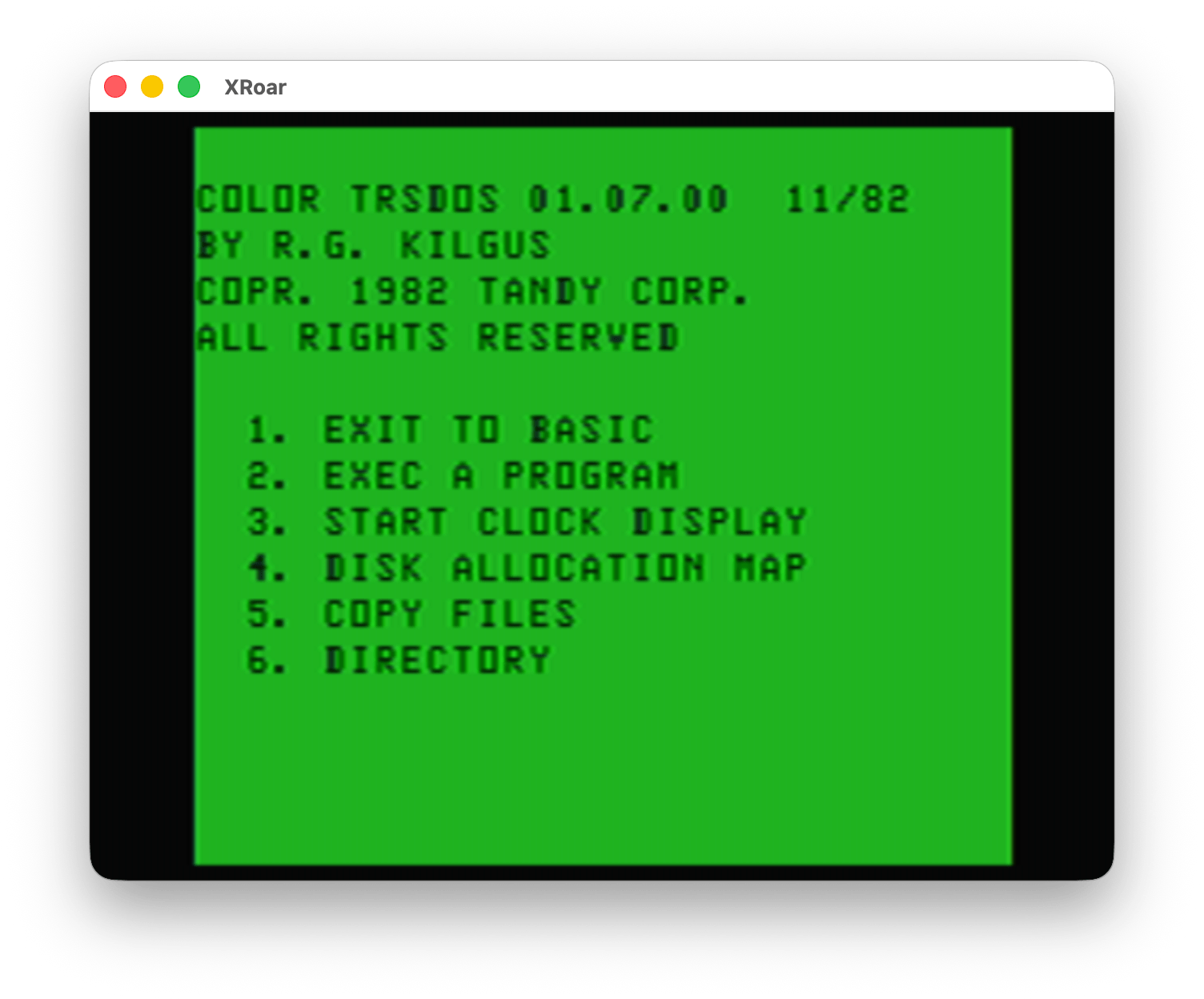
If you do a RUN”DOS” form the Disk EDTASM disk, you are greeted with a menu:
Color TRSDOS – menu
The name “R.G. Kilgus” is instantly recognizable to early adopters of the CoCo. R.G. created some of the earliest Radio Shack programs for to CoCo, including the infamous Dino Wars!
As you may be able to tell from the screenshot, Color TRSDOS was not a DOS like we might expect. Normally, a DOS boots up into a command line that lets you run programs. MS-DOS is probably the most iconic DOS that comes to mind for me:
Instead, Color TRSDOS seemed to be more of a library of disk routines that one could use with their own 6809 assembly programs. BASIC documented a few “official” ROM calls that could be called from assembly routines to do things like print a character to the screen or input a character from the keyboard. DISK BASIC added one that could read or write raw data to a disk. This was very low level, and there was no ROM call to do things like read a directory, create a new file, delete an existing file, or anything else. This means assembly language programmers had to figure that out and write all that code themselves.
Color TRSDOS appears to have been Radio Shack’s official solution for this. You could use the Color TRSDOS assembly language routines in your own programs and get higher level disk functionality, such as the things shown in the Color TRSDOS menu.
Side Note: What was the license agreement for Color TRSDOS? Could that code be included in commercial sold software, or was it only allowed to be used for personal programs? Anyone know?
Maybe I ran into Color TRSDOS in some CoCo program I used over the years. There were certainly many programs that could load/save files to disk and show directories. Maybe some of these made use of the Color TRSDOS routines. Does anyone know of any program that ever used the Color TRSDOS routines?
What could Color TRSDOS do?
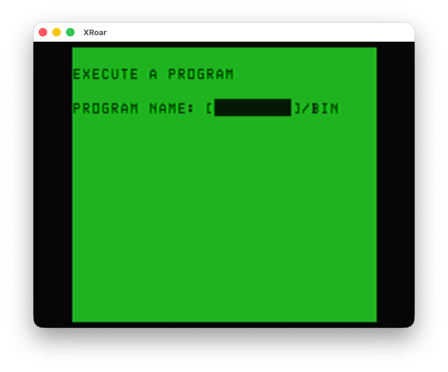
It appears Color TRSDOS has a way to load and execute a binary program, as demonstrated from menu option #2:
Color TRSDOS – Exec a Program
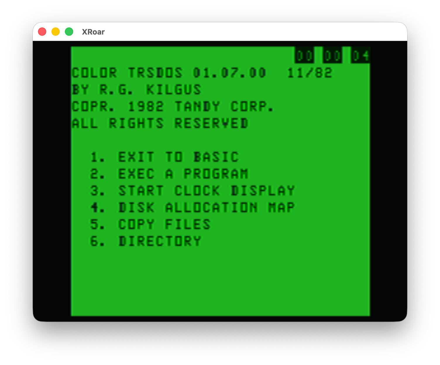
There was also support for a software clock, as demonstrated by menu option #3. It would put an incrementing Hour/Minute/Second value in the top corner of the screen:
Color TRSDOS – Start Clock Display
The Color Computer used the video circuitry to generate a 60Hz signal (also used by the TIMER command in BASIC). It was common for software clocks to make use of this and track time, though this time would drift any time interrupts were masked — such as when accessing a disk.
I have not explored the code myself, but I assume Color TRSDOS just provided a simple software clock for programs to use.
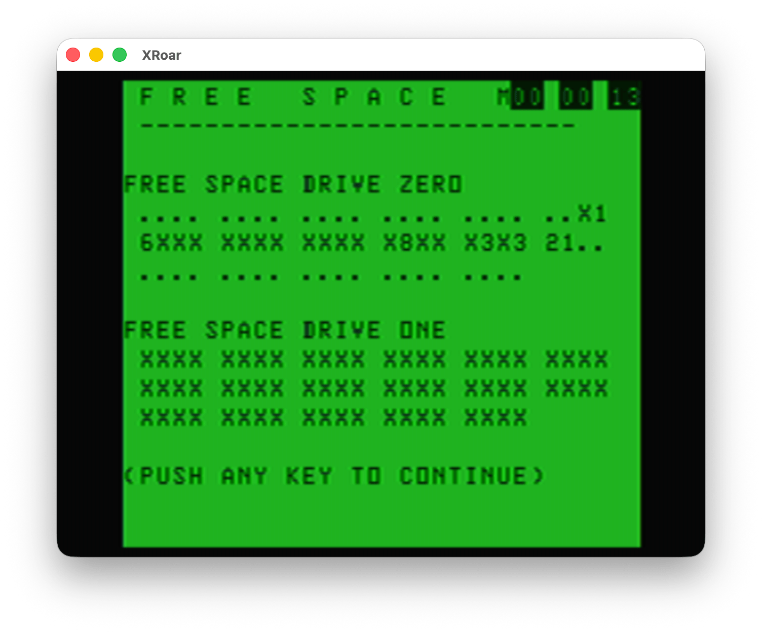
Option #4 would display the Disk Allocation Map. This display showed which granules on the disk were in use. From looking at the display, you can see it represents the 68 granules (9 256-byte sectors, 2304 bytes) that make up an RS-DOS disk. It looks like “.” indicates the granule is free, “X” may indicate all of the 9 of the 256-byte sectors in that granule are used, and a number may indicate how many sectors are used (if less than 9).
Color TRSDOS – Disk Allocation Map (DAM)
I have discussed DISK EXTENDED BASIC’s format and this Disk Allocation Map in previous blog posts. Check that link to learn more about granules and such.
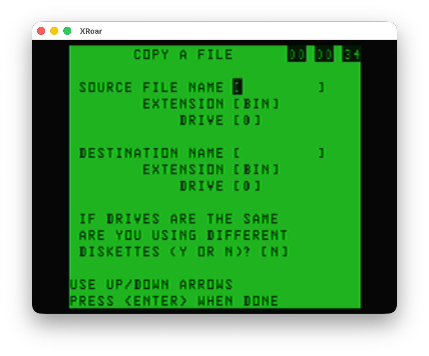
Option #5 showed a simple interface to copy a file, either between the same disk or to separate disks. To copy a file to the same disk in Disk BASIC, you’d do something like this:
COPY "FILE.BAS" TO "NEWFILE.BAS"
This basically duplicated the file, and required a different name for the copy.
To copy a file from Drive 0 to Drive 1:
COPY "FILE.BAS:0" TO "FILE.BAS:1"
But BASIC had no way to copy between separate disks if you only had one disk drive. It looks like this Color TRSDOS program may have a way to do that, where it would read data from the disk, then tell you to swap in the second disk, then write it out there. (I did not test this.)
Color TRSDOS – Copy Files
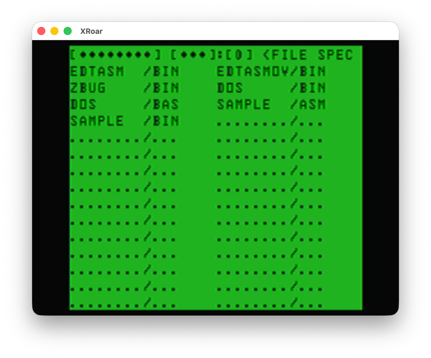
Last, option #6 performed a disk directory. I am unsure how this works, since it initially shows nothing and has some fields where you can type. Perhaps this supported some level of wild cards?
UPDATE: After I wrote this, I went back to try it. You can arrow over to the extension field and enter “BAS” then it only showed the “DOS.BAS” file. Neat! Perhaps wildcard support is built in to the Color TRSDOS routines?
Color TRSDOS – Directory
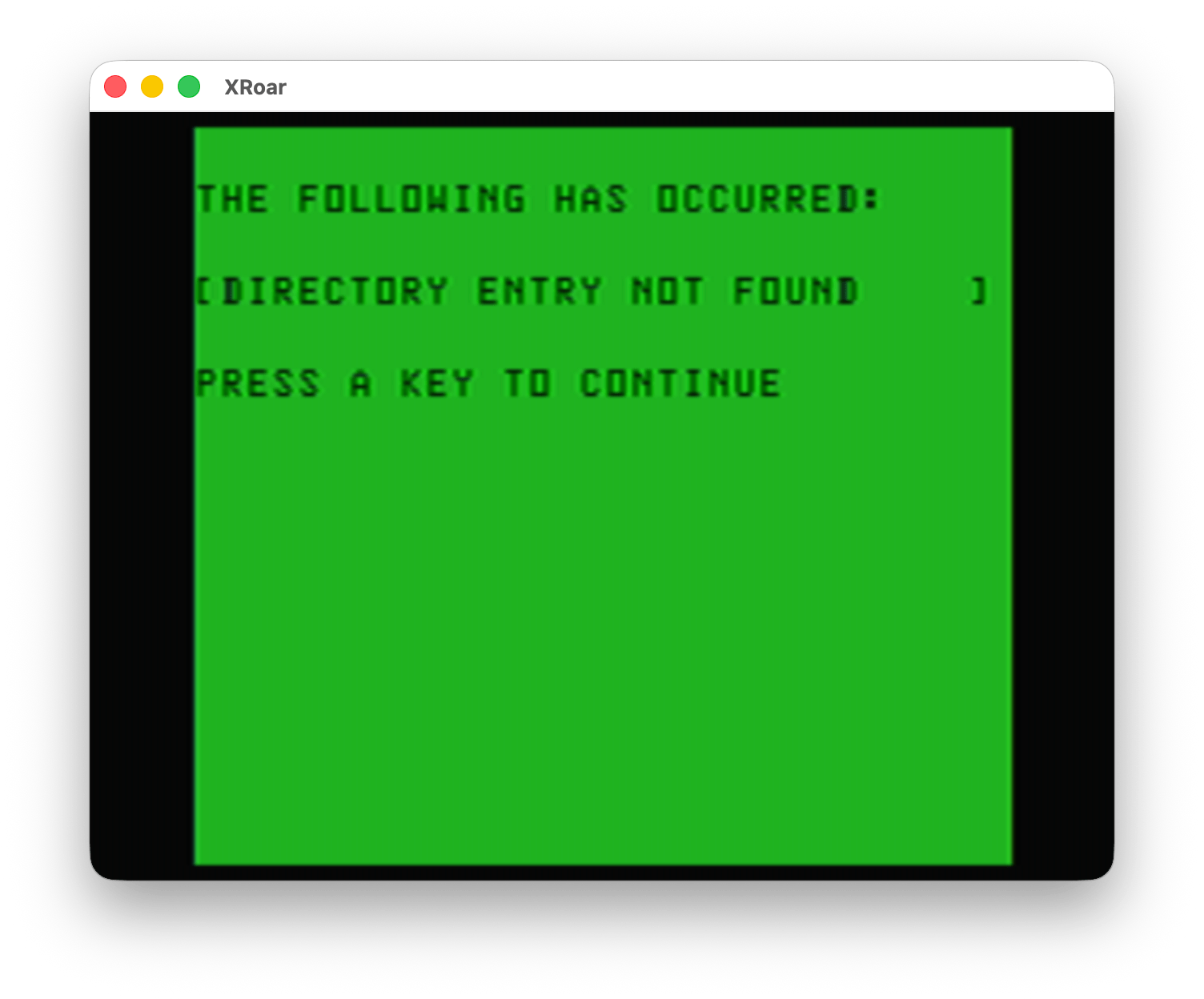
And, of course, error handling…
Color TRSDOS – Error
It looks kinda neat. Had I realized this back then, I could have been adding disk support to my own assembly programs. I really didn’t know it was a thing.
Color TRSDOS is a thing, again!
Well, maybe I get a second chance now. Thanks to the tireless efforts of Abraham Lincoln, Color TRSDOS has been archived to GitHub. In a Facebook CoCo group post dated June 20 2026, he wrote:
“. . . I found an OCR scan of the Disk EDTASM manual and was able to copy-paste the source code from that. There were LOTS and LOTS and LOTS of errors introduced via the OCR scanning process, but I was able to resolve everything, and even correct a bug that was in the original manual (as determined from the non-OCR version) but subsequently fixed in the DOS.BIN executable that shipped with Disk EDTASM.
Now we can generate the exact DOS.BIN executable from source. I went through this exercise so that anyone who is interested can study, learn from, and incorporate the code into their projects, if they’d like. For me, in particular, I wanted to be able to explore it to understand the interface that Tandy expected assembly language developers to use for accessing the disk files so that I could create a command shell that provides the same interface to the programs that it launches.”
– “Abraham Lincoln” on Facebook
Thank you for your service, Abraham! You can find the result of Abraham’s work, as well as progress on a new command line interface, on his GitHub page:
Abraham has also shown the beginning of a command line TRSDOS interface. I look forward to seeing how this turns out. Maybe we will end up with a “real” TRSDOS for the CoCo thanks to his efforts.
When the Insta360 X4 came out, it upgraded the recording format from 5.7K to 8K — basically a 4K image for each of the two lenses. When folks tried to upload these files to YouTube, apparently early on 8K would appear as a choice.
Then something happened.
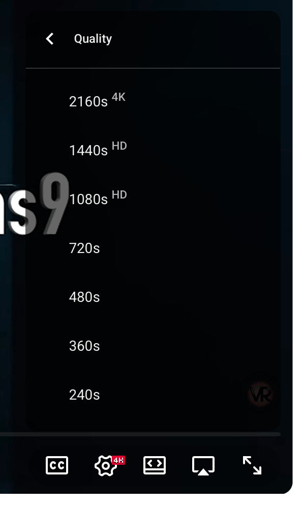
For the past few years I have seen this topic come up time and time again in 360 forums on Facebook, REDDIT, etc. Folks cannot get their videos to show in 8K. Up to 4K is all it offers:
Time and time again, folks in the forum that got it to work just say “sometimes it takes awhile before it shows up.” However, the majority of us seemed to NEVER see this as an option, even months (or a year) later.
Recently, I began investigating this again. I label all my 8K videos as “8K” and it felt misleading to do so if no one could watch them in 8K.
Then I learned: YouTube used a different size for 8K, or so various “experts” claimed. Even though the Insta360 8K size of 7680×3840 worked fine as 8K in the past (for some), apparently now you had to resize the video to 7680×4320 and then and only then would YouTube show it as 8K. At least, according to many folks who were trying to make the work. Here is part of a detailed series of posts on REDDIT about this:
My attempts to do this did not produce 8K. Meanwhile, others still insisted that 8K “just worked” when directly uploading the file exported from Insta360 Studio (and, I would assume, the same size file from the DJI desktop app for the DJI Osmo 360 camera).
But not for most of us.
Does it work for anyone?
I ran into a YouTuber that was posting some 360-degree videos from amusement parks, and noticed they labeled them as 8K in their thumbnails. Yet, no 8K option when I viewed it. This led to a few exchanges in the comments, and them saying they could even see my videos show 8K.
I guess that 7680×4320 suggested by some was not important, after all… even though that is the resolution YouTube specifically mentions for 8K:
When the experts disagree, you know we don’t really know what the rules are.
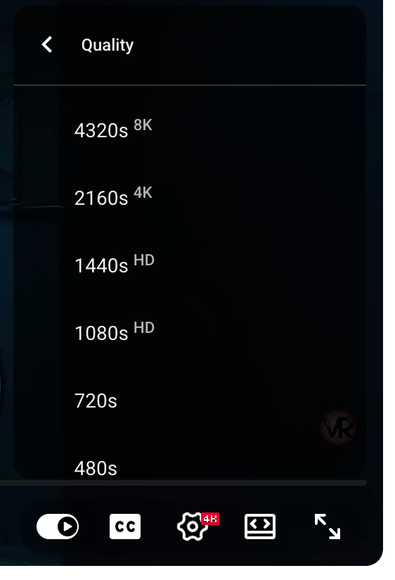
So why is it so many of us cannot see 8K, and others can see it just fine? I was today years old when I actually saw an 8K option or the very first time:
And, then I checked using a different browser on a different operating system (Edge on a Windows 11 machine) and saw it there, too.
Did something get flipped?
Please let me know if you can see an 8K option on the following video — and if you can (or can’t), tell us your browser and operating system. The PC I used was just a low end DELL with no special graphics card, and I am seeing it on an M2 Mac even though I just found a new post saying you needed an M3 or above to see them.
No one seems to know the rules. But one of you may, so let us all know. Thanks!
Hat tip to L. Curtis Boyle for pointing this one out to me. Published in The World of ’68 Micros back in 1995 was an article by John “SockMaster’ Kowalski demonstrating how to do smooth horizontal scrolling on the CoCo 3 in the 320×200 16-color graphics mode.
In BASIC.
With no assembly.
You can find this demo in Volume 2, Number 5 in an article called “The Seven-line demo: an amazing achievement with DECB!” I must have been fully into OS-9 by this point since this article does not seem familiar to me. I was not really keeping up with any BASIC stuff by that point, having moved to OS-9 assembly and C programming.
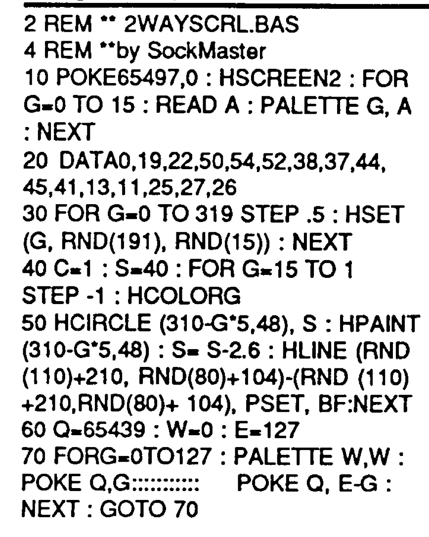
Here is that program as I typed it in and adjusted some spacing, with a few comments added by me. The only crucial part is line 70 which must have 11 colons and five spaces after that POKE Q,G line.
0 'The World of '68 Micros
1 'Volume 2, Issue 5
2 REM ** 2WAYSCRL.BAS
4 REM **bySockMaster
10 POKE 65497,0:HSCREEN 2:FOR G=0 TO 15:READ A:PALETTE G,A:NEXT
20 DATA 0,19,22,50,54,52,38,37,44,45,41,13,11,25,27,26
30 FOR G=0 TO 319 STEP .5:HSET(G,RND(191),RND(15)):NEXT
40 C=1:S=40:FOR G=15 TO 1 STEP-1:HCOLOR G
50 HCIRCLE(310-G*5,48),S:HPAINT(310-G*5,48):S=S-2.6:HLINE(RND(110)+210,RND(80)+104)-(RND(110)+210,RND(80)+104),PSET,BF:NEXT
60 Q=65439:W=0:E=127
65 '11 COLONS, 5 SPACES
70 FOR G=0 TO 127:PALETTE W,W:POKE Q,G:::::::::::     POKE Q,E-G:NEXT:GOTO 70
I am unsure if the other spaces in line 70 are critical. The original listing looked like it had a lot of spaces between keywords and such, but that should not matter. LINE 70, being a loop, would be made a bit slower with extra spaces. Here is how it was presented in the magazine:
Here is what it does when ran in the XRoar emulator:
Spiffy!
Now I am off to read the full article to better understand how this works.
I sometimes see job listings for “embedded programmers,” but when I discover they are using an OS like Linux and a full file system, that does not quite seem “embedded” to me. I hardly consider a Raspberry Pi an “embedded” system. It is more like a desktop system that is small enough to embed.
See also: semantics, pedantic, and “pedantic a–holes” who love to comment about this stuff ;-)
But I digress.
Sometimes I find code in an open source project for an embedded target — such as an Arduino — that just screams “I don’t care about speed.” And, honestly, in most cases you really don’t. But why intentionally be slow?
I ran across a loop that searches for a target string in an index of strings. It was something like this:
int match (const char *name)
{
    int index = -1; // Default to not found.

    for (int idx = 0; idx < COUNT; idx++)
    {
        if (strncmp (array[idx], name, strlen (name)) == 0)
        {
            index = idx;
            break;
        }
    }

    return index;
}
The routine would accept a string and return the index of the first entry in an array that started with the same string. Here is a test program:
/******************************************************************************

Welcome to GDB Online.
  GDB online is an online compiler and debugger tool for C, C++, Python, PHP, Ruby,
  C#, OCaml, VB, Perl, Swift, Prolog, Javascript, Pascal, COBOL, HTML, CSS, JS
  Code, Compile, Run and Debug online from anywhere in world.

*******************************************************************************/
#include <stdio.h>
#include <string.h>

#define COUNT 8

const char *array[COUNT] =
{
    "bacon",
    "eggs",
    "eggs and jam",
    "sausage",
    "pancakes",
    "waffles",
    "toast",
    "coffee"
};


int match (const char *name)
{
    int index = -1; // Default to not found.

    for (int idx = 0; idx < COUNT; idx++)
    {
        if (strncmp (array[idx], name, strlen (name)) == 0)
        {
            index = idx;
            break;
        }
    }

    return index;
}

int main()
{
    int index;

    index = match ("foo");

    printf ("found at: %d", index);

    return 0;
}
If the search target is not found, it returns -1. If the search target matched, it returns the index in the array where the match was found.
I noticed there were no NULL checks and it relied on a #define rather than calculating the array size. This was probably done because the author knew their code was perfect and did not need error checking.
Or maybe they just wanted to save a few lines and some code space.
But the part that bugged me was this:
if (strncmp (array[idx], name, strlen (name)) == 0)
The use of strncmp() each time a compare was done seemed … inefficient. If you had a list of 1000 items, and where looking for a string that was 42 characters long, you would be calculating the length of that string 1000 times by starting at the first byte and moving forward until you found the NULL character at the end. The longer your search string, the slower the search would be.
In these modern times, we don’t really care about things like this. It also might be more important to save a few bytes of code space than use a new variable and pre-calculate the string length.
But when I used this code, I changed it to something like:
int match (const char *name)
{
    int index = -1; // Default to not found.
    size_t length = strlen(name);

    for (int idx = 0; idx < COUNT; idx++)
    {
        if (strncmp (array[idx], name, length) == 0)
        {
            index = idx;
            break;
        }
    }

    return index;
}
I can sleep better now that I know I saved valuable microseconds… ;-)
Exporting an 8K 360 video file that took 43 minutes on an M2 MacBook Air took about 31 minutes on an M4 Mac mini. That is “about 30%” faster, at least for the type of media I am working with.