Please read this tale with a sense of humor ;-) If you ended up on this page by searching for “Arduino account deactivated” or “Arduino wrong email/username or password” or similar, you can skip down to “Potential Solution” to see what you might be able to try…
Background
I created an Arduino account back in 2012 and popped in to the forum from time to time when I was working on a project. My last forum login was 2018. While I wasn’t using their forum often, I still had an Arduino UNO on my desk at work. I use it throughout the year to test 16-bit C code. I just had no reason to post about that mundane use in the forum, so I hadn’t been logging in.
In 2026, I got a new Arduino UNO R4 WiFi. When I tried to check out Arduino Cloud, I found my login did not work. Password recovery never sent a new password, and trying to sign up for a new account told me my username was already in use. Some quick searches revealed Arduino now deactivates accounts if you they are not being used often enough.
Support to the rescue! Well, not really…
I contacted support. They told me they could not reinstate my account. They said I needed to sign up with a new e-mail and create a new username. I pushed back on this. I’ve been using the same e-mail address since 1995 and see no reason to create a new one just for Arduino. Support merely pointed me to their Terms and Conditions:
10.5 Should User be inactive for twenty-four (24) months, Arduino may close their Account for inactivity. The posts made via the inactive Account will remain on the Forum and Project Hub for a period of five (5) years and will continue to identify User during such period via username, and after such five (5) year period such posts will become de-identified by deleting all Personal Data which may directly identify User.
Imagine not visiting Burger King for two years, then seeing some new marketing from their CEO that makes you want to go back and try the new Whopper… and the store tells you:
“Sorry, you haven’t been to Burger King in over 24 months, so we will not allow you back in unless you change your identify.”
Now, I’d like to point out that we agree to weird Terms and Conditions all the time. And companies will change their terms and conditions on us, all the time. We either accept the new terms or stop using the service. This seems fine. They can have whatever terms they wish and those of us that just click “I agree” without reading them can suffer the consequences — such as having your account deactivated.
If I had it to do all over, I would have just set a reminder to “Log in to Arduino” once a year. Problem solved ;-)
Can a company violate its own terms?
Remember, humor. If you are getting wound up by any of this, just remember it’s just some text on a random blog you stumbled into…
The 10.5 section I was pointed to says two things:
“Should User be inactive for twenty-four (24) months, Arduino may close their Account for inactivity.” Yep, they certainly did that. It has been over 24 months since I logged in. They are in compliance. Though, they say “may” so I wish they would have decided to not may for mine.
“The posts made via the inactive Account will remain on the Forum and Project Hub for a period of five (5) years and will continue to identify User during such period via username, and after such five (5) year period such posts will become de-identified by deleting all Personal Data which may directly identify User.” This one seems to be in violation, since 7+ years after my last login, all my information is still there – user profile, profile page, my posts, etc., all attributed to em.
I am bummed they honored #1 which was a “may”, but pleased they did not honor #2, which is a “will”.
Can a company be in violation of their own terms and conditions? Asking for a friend… ;-)
I went back and forth with Arduino Support a few times and eventually was transferred to someone in the “CX Education & Maker Support Team”, whatever that is. They finally gave me a solution, which might be a potential solution for you.
Potential Solution
If your Arduino Forum account is deactivated and you are unable to get back in using a password reset, try this:
Here is an interesting tidbit that I find very customer un-friendly.
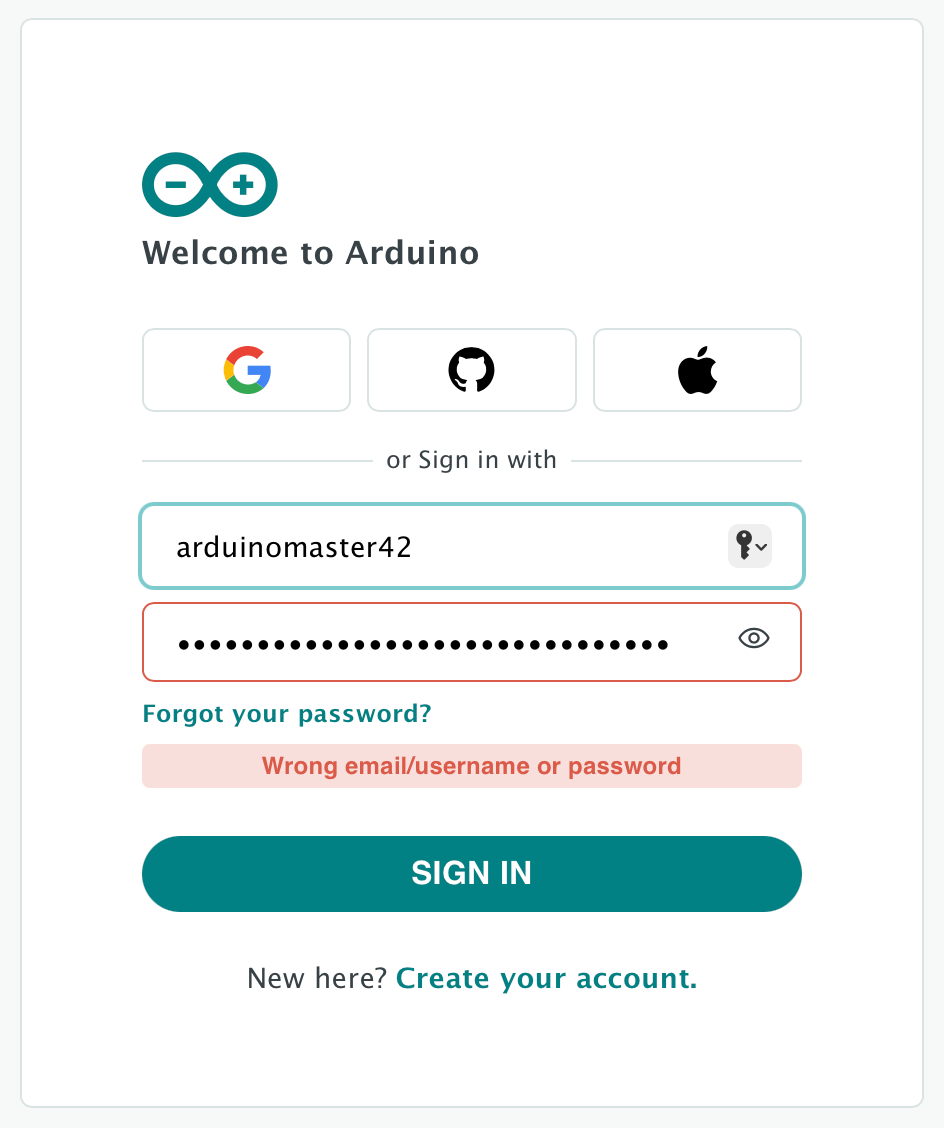
If you have not logged in to your Arduino account in 24 months, they “may” lock your account. If you try to log in after this happens, you will be told “Wrong email/username or password“.
Obviously you will try “Forgot your password.” That will give you the message:
Check your email, we just sent you a link to complete the reset of your password.
…but no e-mail ever shows up.
Some searching revealed they were purging accounts that had not been accessed. I tried to create a new account. As soon as I entered my exciting username, it told me:
This username is reserved: the account was recently deleted for inactivity.
And that led me to contacting their support.
Support says…
Unfortunately, support cannot reinstate old accounts. You have to create a new account using a new e-mail address and a new username. They pointed out it is in the terms of service:
And thus, my account I have had since I first signed up in 2012…
…is now frozen in time, and I have no access to it.
Terms for thee, but not for me?
I last logged in in 2018 – which is over five years ago. Since all my data is still there, and still identified via my username, it looks like Arduino may be in violation of its own terms of service. ;-) They definitely did the part they say they “may” do (close an account for inactivity) but the rest, not so much. That is really frustrating with an account I started 14 years ago.
And, to make matters worse, I have used the same e-mail address since 1995. For me to create a new e-mail address just for this one site and then not have access to all my messages, etc. from the past 14 years is … unfortunate.
Perhaps getting back into Arduino this week was a bad idea ;-)
In conclusion…
Go log in to your Arduino account if you want to keep it.
Over the years, I have posted about things that fall into the category of “how did this ever work?” I think I need to make an actual WordPress Category on this blog for these items, and I will do so with this post.
Every embedded programming job I have had came with a bunch of pre-existing code that “worked.” There are always new features to be added, and bugs to be fixed, but overall things were already at an “it works, ship it” state.
And every embedded programming job I have had came with code that “works” but decided to not work later, leading me down a rabbit hole of code exploring to understand what it did and why it was suddenly did not.
This was often followed by finding a problem in the code that made me wonder how it ever worked in the first place.
SPI and interrupts on the PIC24 processor
This post is not specifically about SPI and interrupts on the PIC24 processor. I just happened to run into this particular issue in that environment.
On the seven hardware systems I maintain code for, there are various devices such as ADC, DAC, EEPROM, attenuators, phase shifters, frequency synthesizers, etc. that are hooked up to the CPU using I/O, I2C or SPI bus.
In the code main loop, the firmware reads or writes to these devices as needed, such as sampling RF detectors or making adjustments to power control attenuators.
Recently, we were testing a pulse modulation mode (PWM) where the RF signal is turning on and off. When on, the power is measured (detector read) inside an interrupt that was tied to the PWM signal. This code has been in place since before I joined 6+ years ago and, other than some bugs and enhancements along the way, “it works.”
However, this SPI code ended up being the cause of some odd problems that initially looked like I2C communications were failing. Our Windows-based host program that communicated over I2C would start having communication faults with the boards running firmware.
After a few days of Whac-A-Mole(tm) trying to rework things that could be problematic, I finally learned the root cause of the issue:
SPI and interrupts
The main loop was doing SPI operations (in our case, using the CCS PCD compiler and its API calls such as spi_init, spi_xfer, etc.). One of those SPI operations was for reading RF detectors. When PWM mode was enabled, the an interrupt service routine would be enabled and the main loop RF detectors reads would shut off and we would begin reading the RF detectors inside the interrupt routine as each pulse happened.
When a SPI operation happens, the code may need to reconfigure the SPI hardware between MODE 0 and MODE 1 transfers, for example, or to change the baud rate.
If the main code configured the SPI hardware for a specific mode and baud then began doing some SPI transfers and the pulse occurred, code would jump into the interrupt routine which might have to reconfigure the hardware differently and then read the detectors. Upon completion, execution returned back to the main loop and the SPI hardware could be in the wrong mode to complete that transaction.
Bad things would happen.
But why now?
The original code allowed pulsing at 100 Hz to 1000 Hz. This meant than 100 to 1000 times a second there was a chance that the SPI hardware could get messed up by the interrupt code. Yet, if we saw this happen, it was infrequent enough to be noticed.
At some point, I modified the code to support 10,000 Hz. This meant there was now 10,000 times a second that the problem could happen.
Over the years we had seen some issues at 10,000 Hz, including what we thought was RF interference causing communication problems (and solved through a hardware modification). Since this mode was rarely used, the true depth of the issue was never experienced.
“It works.”
Simple solutions…
A very simple solution was added which appears to have eliminated this issue completely. Some functions where added that could be called from the main loop code around any access to the SPI hardware. Here is a pseudo-code example of what I added:
Then, inside the interrupt service routine, that code could simply check that flag and skip reading at that pulse, knowing it would just catch the next one (I said this was the simple fix, not the best fix):
void pwm_isr (void)
{
    if (0 == g_spi_lock) // SPI is free.
    {
        // Do SPI stuff…
    }
}
Then all I had to do was add the claim and release around all the non-ISR SPI code…
“And just like that,” the problems all went away. Many of the problems we had been unaware of since some — like doing an EEPROM read — were typically not done while a system was running with RF enabled and pulsing active. Once I learned what the problem was, I could recreate it within seconds just by doing various things that caused SPI activity while in PWM mode. ;-)
That was my quick-and-dirty fix, but you may know a better one. If you feel like sharing it in a comment, please do so.
But the question remains…
How did this ever work?
Once the bug was understood, recreating it was simple. Yet, this code has been in use for years and “it worked.”
My next task is going to be reviewing all the other firmware projects and seeing if any of them do any type of SPI or I2C stuff from an interrupt that could mess up similar code happening from the main loop.
And I bet I find some.
In code that “just works” and has been working for years.
Finding out how to do this was a confusing mess. There are dozens (if not hundreds) of messages and blog posts describing how it should work, but none matched my situation enough to actually work for me. Amazingly, the search engine A.I.s were most helpful in figuring it out, but for those who prefer a human (I assume), this blog post has the important details:
I thought I would summarize the steps it takes to have a Synology NAS (like a DS1522+) user home directory on a Raspberry Pi.
Synology NAS Steps
My main system is a Mac and I enable the SMB service on my Synology NAS. This is the file sharing service that will let you access your NAS from a PC (“\\NASName”) or Mac (smb://NASName). On Mac, this is what lets me browse to my NAS through the Finder:
I find that a super-convenient way to do it since I can have my Mac always prompt me for a username and password, or have it remember them in the keychain/passwords app if I don’t want security. . .
1. Enable SMB
Log in to your Synology, then go to Control Panel -> File Services -> SMB Tab
Enable the SMB service. You can also specify a custom Workgroup name, such as “WORKGROUP.”
You may also want to enable the Bonjour service in the Advanced tab. That should make it show up to your Mac without having to know its IP address. For this demo, my NAS is named “DS1522” and Bonjour is what (I believe) makes that show up in my Finder.
2. Create a User on the Synology NAS
You can create a new user account which will have its own isolated home directory.
Control Panel -> User & Groups – Create Tab
You can create a new user account with its own password. I used my e-mail address so I can get any notifications (such as password reset).
After clicking Next, you get a chance to assign this new user to any specific groups. You should have “users / System default group” already checked. If not, make sure to check it.
On the next Next screen, make sure this new user has Read/Write Access to the homes group. You will want to check that one yourself:
The next few screens are for specific permissions. I left them at defaults since all I am using this account for is a shared folder. Eventually, it will Save and you will have the new user.
Now with this user created, you should be able to browse to it and login using that username and password and see the home folder. You can access it in Finder (if Bonjour is active) or type Command+K from a Finder window and enter “smb://” and the IP address of your NAS (“smb://10.0.0.1” or if it has a name, “smb://NASName”) and you should get prompted for a username and password:
Once connected, you should be able to get to that user’s home folder (under homest) and see whatever is is there Your new account will be empty, but I have already copied some files into mine. Those files are stored on my NAS, but I can connect and get to them from my Mac.
Now we will get the Raspberry Pi to connect and see those files, too.
Raspberry Pi Steps
The current Pi operating system has the stuff to do this built-in, but if you have an older OS, you may have to install some things. I can’t cover that, since I did not need to.
At this point, you should be able to mount the new user account on your Pi just by typing in a command like this:
The “//ds1522.local” should be the name of your NAS or the IP address (if not using Bonjour). After that is the path to where the home folder for the new account is. Those are in “/homes/accountname”.
The “/home/allenh/DS1522” is the destination where the folder will me mounted on the Raspberry Pi. In my case, my Pi account name is “allenh” and I wanted it in a folder called “DS1522” in my home folder there — “/home/allenh/DS15222”.
After that, “username=” can be set with the user account to log in to, or just have “username=” if you want to b prompted for the username.
Then comes where you could have also specified a password using “password=” and the password. But that shows your password to anyone able to see you typing on the screen.
You then give whatever workgroup name you set up in SMB sharing on the Synology NAS.
After that, I found I had to include the “rw” read/write flag, else I could only read files, and if I tried to write anything out I got a Permission Error.
The next bit with “uid” (user I.D.) and “gid” (group I.D.) may or may not be necessary, but after mine only gave me READ access, I asked some of the A.I.s and they suggested that and it worked. I don’t really know what that is for, but “it worked for me.”
After this, you should get prompted for the password of that Synology account, and then you should see that remote home folder appear on your PI.
Un-mounting
To unmount/release this mapped in folder, use “sudo umount -l /home/allenh/DS1522“.
If you forget what all you have mounted, you can type “df -h” to see a list of all things mounted to the Pi.
Scripting
To make things easier, I created a simple shell script called “mountnas.sh” that contains the command I use. I also made an “unmount.sh” script with the unmount command.
Now, if my Pi is on the same network as my NAS, I can just run one of those scripts or type the command and get that folder mounted so I can read/write files to it from my Pi.
NOTE: This article was originally written two years ago, and meant to be part of a series. I never got around to writing Part 2, so I am just publishing this initial part by itself. If there is interest, I will continue the series. My Github actually shows the rest of the work I did for my “full” and “small” version of the driver code for this LCD.
Recently, my day job presented me an opportunity to play with a small 20×4 LCD display that hooked up via I2C. The module was an LCD2004. The 20 is the number of columns and the 04 is the number of rows. The LCD1602 would be a 16×2 display.
While I have found many “tutorials” about these displays, virtually all of them just teach you how to download a premade Arduino library and use library functions. Since I was going to be implementing code for an in-house project, and did not have room for a full library of functions I would not be using, I really needed to know how the device worked. Hopefully this article may help others who need (or just want) to do what I did.
LCD2004 / LCD1602 / etc.
These LCD modules use a parallel interface and requires eleven I/O pins. The pinout on the LCD looks like this:
A few of the pins are listed by different names based on whoever created the data sheet or hardware. On my LCD2004 module, pins 15 and 16 are listed as A and K, but I now know they are just power lines for the backlight.
If you have something like an Arduino with enough available I/O pins, you can wire the display up directly to pins. You should be able to hook up power (5V to VDD, Ground to VSS, and probably some power to the backlight and maybe something to control contrast), and then connect the eight data lines (D0-D7) to eight available digital I/O pins on the Arduino.
The LCD module has a simple set of instruction bytes. You set the I/O pins (HIGH and LOW, each to represent a bit in a byte), along with the RS (register select) and RW (read/write) pins, then you toggle the E (Enable) pin HIGH to tell the LCD it can read the I/O pins. After a moment, you toggle E back to LOW.
The data sheets give timing requirements for various instructions. If I read it correctly, it looks like the E pin needs to be active for a minimum of 150 nanoseconds for the LCD to read the pins.
Here is a very cool YouTube video by Ian Ward that shows how the LCD works without using a CPU. He uses just buttons and dip switches. I found it quite helpful in understanding how to read and write to the LCD.
If you don’t have 11 I/O pins, you need a different solution.
Ian Ward’s excellent LCD2004 video.
A few pins short of a strike…
If you do not have eleven I/O pins available, the LCD can operate in a 4-bit mode, needing only four pins for data. You send the upper four bits of a byte using the E toggle, followed by the lower 4-bits of the byte. This is obviously twice as slow, but allows the part to be used when I/O pins are limited.
If you don’t have 7 I/O pins, you need a different solution.
PCF8574: I2C to I/O
If you do not have seven I/O pins available, you can use the PCF8574 chip. This chip acts as an I2C to I/O pin interface. You write a byte to the chip and it will toggle the eight I/O pins based on the bits in the byte. Send a zero, and all pins are set LOW. Send a 255 (0xff) and all pins are set HIGH.
Using a chip like this, you can now use the 2-wire I2C interface to communicate with the LCD module–provided it is wired up and configured to operate in 4-bit mode (four pins for data, three pins for RS, RW and E, and the spare pin can be used to toggle the backlight on and off).
Low-cost LCD controller boards are made that contain this chip and have pins for hooking up to I2C, and other pins for plugging directly to the LCD module. For just a few dollars you can buy an LCD module already soldered on to the PCF8574 board and just hook it up to 5V, Ground, I2C Data and I2C Clock and start talking to it.
If you know how.
I did not know how, so I thought I’d document what I have learned so far.
What I have learned so far.
The PCF8574 modules I have all seem to be wired the same. There is a row of 16-pins that aligns with the 16 pins of the LCD module.
PCF8574 module.
One LCD I have just had the board soldered directly on to the LCD.
LCD2004 with the PCD8574 module soldered on.
Another kit came with separate boards and modules, requiring me to do the soldering since the LCD did not have a header attached.
PCF8574 module and LCD1602, soldering required.
If you are going to experiment with these, just get one that’s already soldered together or make sure the LCD has a header that the board can plug in to. At least if you are like me. My soldering skills are … not optimal.
The eight I/O pins of the PCF modules I have are connected to the LCD pins as follows:
1 - to RS
2 - to RW
3 - to E
4 - to Backlight On/Off
5 - D4
6 - D5
7 - D6
8 - D7
If I were to send an I2C byte to this module with a value of 8 (that would be bit 3 set, with bits numbers 0 to 7), that would toggle the LCD backlight on. Sending a 0 would turn it off.
That was the first thing I was able to do. Here is an Arduino sketch that will toggle that pin on and off, making the backlight blink:
// PCF8574 connected to LCD2004/LCD1602/etc.
#include <Wire.h>

void setup() {
  // put your setup code here, to run once:
  Wire.begin ();
}

void loop() {
  // put your main code here, to run repeatedly:
  Wire.beginTransmission (39); // I2C address
  Wire.write (8); // Backlight on
  Wire.endTransmission ();

  delay (500);

  Wire.beginTransmission (39); // I2C address
  Wire.write (0); // Backlight off
  Wire.endTransmission ();

  delay (500);
}
Once I understood which bit went to which LCD pin, I could then start figuring out how to talk to the LCD.
One of the first things I did was create some #defines representing each bit:
We’ll use this later when building our own bytes to send out.
Here is a datasheet for the LCD2004 module. Communicating with an LCD1602 is identical except for how many lines you have and where they exist in screen memory:
I actually started with an LCD1602 datasheet and had it all working before I understood what “1602” meant a different sized display than whatI had ;-)
Sending a byte
As you can see from the above sample code, to send an I2C byte on the Arduino, you have to include the Wire library (for I2C) and initialize it in Setup:
#include <Wire.h>

void setup() {
  // put your setup code here, to run once:
  Wire.begin ();
}
Then you use a few lines of code to write the byte out to the I2C address of the PCF8574 module. The address is 39 by default, but there are solder pads on these boards that let you change it to a few other addresses.
Communicating with the LCD module requires a few more steps. First, you have to figure out which pins you want set on the LCD, then you write out a byte that represents them. The “E” pin must be set (1) to tell the LCD to look at the data pins.
After a tiny pause, you write out the value again but with the E pin bit unset (0).
That’s all there is to it! The rest is just understanding what pins you need to set for what command.
Instructions versus Data
The LCD module uses a Register Select pin (RS) to tell it if the 8-bits of I/O represents an Instruction, or Data.
Instruction – If you set the 8 I/O pins and have RS off (0) then toggle the Enable pin on and off, the LCD receives those 8 I/O pins as an Instruction.
Data – If you set the 8 I/O pins and have RS on (1) then toggle the Enable pin on and off, the LCD received those 8 I/O pins as a Data byte.
Reading and Writing
In addition to sending Instructions or Data to the LCD, you can also read Data back. This tutorial will not cover that, but it’s basically the same process except you set the Read/Write pin to 1 and then pulse the E pin high/low and then you can read the pins that will be set by the LCD.
Initialize the LCD to 4-bit mode
Since only 4 of the PCF8574 I/O pins are used for data, the first thing that must be done is to initialize the LCD module to 4-bit mode. This is done by using the Function Set instruction.
Function set is described as the following:
RS  RW  DB7 DB6 DB5 DB4 DB3 DB2 DB1 DB0
--- --- --- --- --- --- --- --- --- ---
0   0   0   0   1   DL  N   F   x   x
Above, RS is the Register Select pin, RW is the Read/Write pin, and DB7-DB0 are the eight I/O pins. For Function Set, pins DB7-DB5 are “001” representing the Function Select instruction. After that, the pins are used for settings of Function Select:
DB4 is Data Length select bit. (DL)
DB3 is Number of Lines select bit
DB2 is Font select bit
When we are using the PCF8574 module, it ONLY gives us access to DB7-DB4, so it is very smart that they chose to make the DL setting one of those four bits. We have no way to access the pins for N or F until we toggle the LCD in to 4-bit data length mode.
If we were using all 8 I/O pins, we’d set them like this to go in to 4-bit mode:
That sequence will initialize the LCD so we can send it commands. After that, we can use Function Set to change it to 4-bit mode (DB4 as 0 for 4-bit mode):
If we used all 8 I/O pins directly, we could also set Font and Number of lines at the same time after the three initializing writes. BUT, since we are using the PCD8547 and only have access to the top four bits (DB7-DB4), we must put the LCD in to 4-bit mode first. More details on how we use that in a moment.
If I wanted to initialize the LCD, I would just need to translate the I/O pins into the bits of a PCF8574 byte. For the first three initialization writes, it would look like this:
ABove, you see only need to pass in the bit pattern for DB7 DB6 DB5 DB4. This routine will set the Backlight Bit (it doesn’t have to, but I didn’t want the screen to blank out when sending these instructions), and then write the byte out with the E pin set, pause, then write it out again with E off.
Thus, my initialization can now look like this:
// Initialize all pins off and give it time to settle.
Wire.beginTransmission(PCF8574_ADDRESS);
Wire.write(0x0);
Wire.endTransmission();

delayMicroseconds(50000);

// [7  6  5  4  3  2  1  0 ]
// [D7 D6 D5 D4 BL -E RW RS]
LCDWriteInstructionNibble(0b0011);
delay(5); // min 4.1 ms

LCDWriteInstructionNibble(0b0011);
delayMicroseconds(110); // min 100 us

LCDWriteInstructionNibble(0b0011);
delayMicroseconds(110); // min 100 us

// Set interface to 4-bit mode.
LCDWriteInstructionNibble(0b0010);
That looks much more obvious, and reduces the amount of lines we need to look at since the function will do the two writes (E on, E off) for us.
Sending 8-bits in a 4-bit world
Now that the LCD is in 4-bit mode, it will expect those four I/O pins set twice — the first time for the upper 4-bits of a byte, and then the second time for the lower 4-bits. We could, of course, do this manually as well by figuring all this out and building the raw bytes outselves.
But that makes my head hurt and is too much work.
Instead, I created a second function that will send an 8-bit value 4-bits at a time:
You’ll notice I pass in the Register Select bit, which can either be 0 (for an Instruction) or 1 (for data). That’s jumping ahead a bit, but it makes sense later.
I can then pass in a full instruction, like sending Function set to include the bits I couldn’t set during initialization when the LCD was in 8-bit mode and I didn’t have access to DB3-DB0. My LCDInit() routine set the LCD to 4-bit mode, and then uses this to send out the rest of the initialization:
// Function Set
// [0  0  1  DL N  F  0  0 ]
// DL: 1=8-Bit, 0=4-Bit
//  N: 1=2 Line, 0=1 Line
//  F: 1=5x10, 0=5x8
//             [--001DNF00]
LCDWriteByte(0, 0b00101000); // RS=0, Function Set

// Display On
// [0  0  0  0  1  D  C  B ]
// D: Display
// C: Cursor
// B: Blink
//             [--00001DCB]
LCDWriteByte(0, 0b00001100); // RS=0, Display On

// Display Clear
// [0  0  0  0  0  0  0  1 ]
LCDWriteByte(0, 0b00000001);
delayMicroseconds(3);  // 1.18ms - 2.16ms

// Entry Mode Set
// [0  0  0  0  0  1  ID S ]
// ID: 1=Increment, 0=Decrement
//  S: 1=Shift based on ID (1=Left, 0=Right)
//             [--000001IS]
LCDWriteByte(0, 0b00000110);
To make things even more clear, I then created a wrapper function for writing an Instruction that has RS at 0, and another for writing Data that has RS at 1:
// Entry Mode Set // [0 0 0 0 0 1 ID S ] // ID: 1=Increment, 0=Decrement // S: 1=Shift based on ID (1=Left, 0=Right) // [--000001IS] LCDWriteInstructionByte(0b00000110);
The Display Clear instruction is 00000001. There are no other bits that need to be set, so I can clear the screen by doing “LCDWriteInstructionByte (0b00000001)” or simply “LCDWriteInstructionByte(1)”;
Ultimately, I’d probably create #defines for the different instructions, and the settable bits inside of them, allowing me to build a byte like this:
FUNCTION_SET would represent the bit pattern 0b00100000, and the DL_BIT would be BIT(4), N_BIT would be BIT(3) and F_BIT would be BIT(2). Fleshing out all of those defines and then making wrapper functions would be trivial.
But in my case, I only needed a few, so if you wanted to make something that did that, you could:
This type of thing can allow your code to spiral out of control as you create functions to set bits in things like “Display On/Off Control” and then write wrapper functions like “LCDDisplayON()”, “LCDBlinkOn()” and so on.
But we won’t be going there. I’m just showing you the basic framework.
Now what?
With the basic steps to Initialize to 4-Bit Mode, then send out commands, the rest is pretty simple. If you want to write out bytes to be displayed on the screen, you just write out a byte with the Register Select bit set (for Data, instead of Instruction). The byte appears at whatever location the LCD has for the cursor position. Simple!
At the very least, you need a Clear Screen function:
The last thing I implemented was a thing that sets the X/Y position of where text will go. This is tricky because the display doesn’t match the memory inside the screen. Internally my LCD2004 just has a buffer of screen memory that maps to the LCD somehow.
The LCD data is not organized as multiple lines of 20 characters (or 16). Instead, it is just a buffer of screen memory that is mapped to the display. In the case of the LCD2004, the screen is basically 128 bytes of memory, with the FIRST line being bytes 0-19, the SECOND line being bytes 64-83, the THIRD line being bytes 20-39, and the FOURTH line being bytes 84-103.
If you were to start at memory offset 0 (top left of the display) and write 80 bytes of data (thinking you’d get 20, 20, 20 and 20 bytes on the display), that wouldn’t happen ;-) You’d see some of your data did not show up since it was writing out in the memory that is not mapped in to the display. (You can also use that memory for data storage, but I did not implement any READ routines in this code — yet.)
If you actually did start at offset 0 (the first byte of screen memory) and wrote a series of characters from 32 (space) to 127 (whatever that is), it would look like this:
Above, you can see the first line continues on line #3, and then after the end of line 3 (…EFG” we don’t see any characters until we get to the apostrophe which displays on line 2. Behind the scenes, memory looks like this:
All you need to know is that the visible screen doesn’t match LCD memory, so when creating a “set cursor position” that translates X and Y to an offset of memory, it has to have a lookup table, like this one:
You will see I created a function that sends the “Set Offset” instruction (memory location 0 to 127, I think) and then a “Set X/Y” function that translates columns and rows to an offset.
With all that said, here are the routines I cam up with. Check my GitHub for the latest versions:
The LCDTest.ino program also demonstrates how you can easily send an Instruction to load character data, and then send that data using the LCDWriteData functions.
I plan to revisit this with more details on how all that works, but wanted to share what I had so far.
I am in the slow process of upgrading five WD 6TB hard drives in my Synology DS1522+ NAS to Seagate 8TB drives. While folks I asked overwhelming say the larger drives (16TB, 20TB, etc.) “have not had any issues,” I am old school and do not want to make that large of a storage jump just yet. For those as data paranoid as I am, some tips:
Do a low-level format (or “secure erase”) on each new drive first. This will write to every sector, and can catch issues. I have only caught one (or maybe two) drive with issues of the years, but the time spent is worth it to me. I’d rather catch a problem before I install and send them back for a replacement, rather than having an issue show up much later (possibly when the drive is out of warranty).
Until someone can say that a “20TB” drive is as reliable as a smaller drive, upgrage to the next size up that gives you enough storage. The less dense the data, the safer it “should” be. Also, if a 6TB drive fails, the rebuild time to replace it will be significantly faster than replacing a 20TB drive. And, during the rebuilt time, your data is at risk. I run dual drive redundancy so during the 12 hours my NAS rebuilds, if I have a second drive fail, I am still okay… but if that happens I have no protection from a third failure. Doing 20 hours rebuilds creates a much larger window for data loss if something goes terribly wrong.
And, of course, make sure anything important is on a backup drive (I use a standalone 10TB just to clone my most important “can’t live without” data), and have an offsite backup of that (I then have that entire drive backed up to a cloud backup service).
If my home burns down, I should at least be able to get back the 10TB of “can’t live without” data from my offsite backup.
Hardware Redundancy is Better
Sadly, Synology units are much more expensive than my Drobos were. My Drobo 5C was $300 retail. I had two that I paid maybe $250 each for. That let me have two 5-bay units for hardware redundancy. This means if a Drobo suddenly died, I still had a second unit with duplicate data (I would sync the two drives). Spending $500 for two 5-drive units was an easier investment than the $1400 it would take for me to buy two DS1522+.
Eventually I do plan to have a duplicate Synology unit. It doesn’t matter what features the device has if one morning it has died. I would have zero access to my data until the unit is replaced or repaired. Having backup hardware is what I prefer.
But I am data paranoid.
How about you? Are you unlucky, like I am, and have had drives “die suddenly” over the years? After that happens enough, the paranoia sets in. I can’t think of a time in the past decades where I didn’t have three backups of everything important ;-)
Prototype “Sir Sound” sound module for the CoCo (or anything with a serial port, actually).
So … many … wires.
At the time, I was hoping to find some kind of Arduino emulator so I could write and test code without hooking up hardware. I found nothing.
But that seems to have changed. I just learned about Wokwi which allows one to “simulate IoT projects in your browser.” In a nutshell, it’s a website that has a code editor (which appears to be Microsoft Visual Studio Code), compiler, and virtual target hardware like Arduino and ESP32 devices. It even supports some add-on hardware, like buttons, LCD displays, LEDs and more.
Here’s a project someone made that simulates an Arduino hooked to a numeric keypad and LCD display:
And you can build and run it right there!
There is a library of devices that are supported, and you can add them to your project and wire them up to the computer’s I/O pins. For example, as I write this blog post, I opened up a starter project that is an Arduino and a two-line LCD display. I then added a pushbutton to it.
I could then move the button to where I wanted it, then click on the connectors and draw wire lines between it and I/O pins on the Arduino. By hooking one side to an I/O pin, and the other to ground, I could then modify the program to read that button and, for this example, increment a counter while the button is being held done.
It’s just that easy! I had no idea!
The files can be downloaded and used on real hardware, or you can make an account and log back in to continue working on them. (It has an unusual way to log in — it sends you an e-mail and you click a link to log in, rather than having a username and password. This seems to mean I cannot log in from any system that I don’t have my e-mail account configured on, but I do see options for using a Google or Github login.)