
Updates:
- 2018-03-02: Making link to separate article on installing firmware easier to notice.
- 2018-07-28: Travis Poppe has a 3-D printed case for this you can download and print: https://www.thingiverse.com/thing:2923619
- 2020-05-01: Reformatting for current WordPress. Renaming some images.
This is a fairly detailed guide to configuring a cheap ESP8266 WiFI module to act as a WiFi modem, then wiring it up to any computer with a traditional RS-232 port.
It can be as simple as hooking up four wires, or many more wires, or even making a breadboard prototype:

ESP8266 to “3-wire” RS-232 TTL adapter. 
Wiring up a “full” RS-232 to TTL adapter. 
ESP8266 to RS-232 on a breadboard.
Hardware Needed
- ESP82660-12E NodeMCU 1.0 development module (or a NodeMCU ESP-32S module)
- microUSB cable and power source (either powered by a computer’s USB port, or a standalone USB power supply like a phone charger)
- RS-232 to TTL adapter that operates at 3.3V.
- Female-to-female jumper wires (or male-to-male jumper wires and a breadboard)
- RS-232 cable (and possibly an RS-232 gender changer or NULL modem adapter)
Software Needed
Currently, we have to download and build the special Zimodem firmware, but as soon as I figure out what it takes just to load a pre-built binary, this section will be removed.
- Serial Drivers for the development module you choose.
- Zimodem firmware for the ESP by Bo Zimmerman.
- ESP firmware flash tool (or Arduino IDE if you want to download and build the source code yourself).
HARDWARE
ESP Development Module
The ESP8266 is a tiny WiFi device that can also run custom code. The development module version has a built-in USB-Serial adapter that can be used for debugging and loading firmware, and also gives a convenient way to power the module.
- I started out with a NodeMCU ESP8266-12E module from Amazon for $8.29, available with 2-day Prime shipping. I later ordered a batch of five for $25 from this e-Bay reseller (shipped from the US). You can also find them for under $4 each if shipped from China.
- The ESP32 is also supported, like this ESP32-WROOM-32 NodeMCU 32-S module for $12.99 on Amazon. They can be also be found for under $6 shipped from China. The ESP32 adds support for Bluetooth, but the firmware we will be using currently does not make use of it. The only real reason to use it is that Zimodem for ESP32 will be built using standard RS-232 signals, while the Zimodem build for ESP8266 has inverted RS-232 signals for Commodore computers, and will require some additional setup to make work on non-Commodore machines.
- Even an under-$2 ESP-01 will work if you are not needing full RS-232 signals like hardware flow control and carrier detect. However, you will need more hardware to program it and power it, so I just stick with one of the development boards that has USB built in. (It actually cost me more to order an ESP-1 plus the USB programming adapter than to buy one of the devkits with everything built in.)
microUSB Cable and power supply
You will need a standard USB to microUSB cable to hook the ESP to a computer so you can load the firmware. Most Android phones use this type of cable, as do things like the Raspberry Pi. If you don’t have one, you can probably buy one at the local gas station.
This cable will also provide power for the ESP module, so it will need to be hooked to a computer’s USB port, or into a USB power supply like a phone charger. Again, commonly available even at the local gas station.
RS-232 to TTL Adapter
The ones I found have a standard DB9 female connector and contain circuitry that will convert the 3.3V chip-level TTL signals used by the ESP chip to standard 12V RS-232 levels that a computer uses. These will often will come with a short 4-wire jumper cable that can be used to hook them up to the ESP module.
- If all you want is just transmit and receive (referred to as a “3-wire” hookup), you can go with a simple one like this $7 one from Amazon (there are also ones under $6), or find them for less with slower shipping (under $1 shipped from China). These provide hookups for TX (transmit), RX (receive), VCC (power) and GND (ground). For simple uses, this may be all you need. MAKE SURE THE ADAPTER SUPPORTS 3.3V! Some only work with 5V and are not compatible with the ESP modules. WARNING: Some of the ones I tried that claimed they operated at 3.3V did not, so it may take some trial and error.
- If you also need hardware flow control (referred to as a “5-wire” hookup), there are adapters that a add extra connections for CTS and RTS. They are usually cost just a dollar or so more. (Here is a $10 one from Amazon, but I’ve found them for under $4 on eBay.)
- If you need full RS-232 signals, including carrier detect, I have found two sources of adapters that provide TX (transmit), RX (receive), DCD (data carrier detect), CTS (clear to send), RTS (request to send), DTR (data terminal ready), DSR (data set ready), and RI (ring indicator).
- Pololu 23201a Serial Adapter – available asssembled for $11.50, or in a partial kit for $9.95. This adapter uses one row of 10 pins, and is breadboard friendly. However, I have had been some issues with this part, so I cannot currently recommend it. If you try it and can get it to work, please let me know.
- AIBANS.BREAKOUT Adapter – available through Amazon for $4.68+$3.03 shipping from California reseller MD Fly, or $3.25+$3.65 standard shipping through their e-Bay listing. (On eBay, you can get a shipping discount for ordering multiple units.) This one works great for me, but it uses a dual-row of pins so it is not breadboard friendly.

“3-wire” RS-232 to TTL adapters, providing just TX and RX. 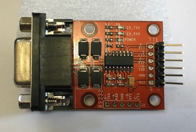
“5-wire” RS-232 to TTL adapter, adding CTS and RTS for flow control. 
Full RS-232 to TTL adapters, providing all signals (TX, RX, CTS, RTS, DTR, DSR, DCD, RI).
Jumper Wires (Female-to-Female)
Most of the RS-232 to TTL adapters I have seen come with a set of jumper wires with female ends. They slide over the pins on the board, and then slide over the pins of whatever you are connecting it to. They allow hooking up parts without needing soldering skills or even a breadboard. I find bundles of 40 of these for under $3.

Optional: Breadboard and Male-to-Male Jumper Wires
Optionally, if you want something that is a bit more “stable” (without exposed pins and such), you can use a breadboard and male-to-male jumper wires, then plug everything up and jumper them together.
RS-232 Cable and Adapters
You will need a cable to go from your computer’s RS-232 port to the adapter. Your cable will depend on the type of RS-232 to TTL adapter you have. All the ones I have use DB-9 female connectors, but there are some that use a male connector.
For example, my Radio Shack Color Computer has a 4-pin DIN connector for the built-in Serial I/O port. Back then, cables where made that had a male 4-pin DIN connector on one end (to plug into the CoCo) and a male DB-25 connector on the other (to plug into a modem). If I could find my old cables, I could use them, but I would still need a DB-25 to DB-9 adapter to go between that cable and the smaller DB-9 connector of the RS-232 to TTL adapter.
Another common type of serial cable is a NULL modem cable, which was used to hook two computers together by serial ports. I have a NULL modem cable that has the male 4-PIN DIN connector on one end and a female DB-9 on the other. Since it is a NULL modem cable, it has the TX and RX lines swapped so it can plug directly to a “modern” PC’s serial port DB-9 male connector. To use this cable, I needed a male DB-9 to male DB-9 NULL modem adapter, which will swap the TX and RX again, making it a normal cable like the RS-232 to TTL adapter requires, and change the gender so it will plug into the TTL adapter.
I also have the Deluxe RS-232 Program Pak, which provides a full RS-232 port with a female DB-25 connector. To use that, I ordered a standard male DB-25 to male DB-9 cable from Amazon. This will plug directly from my RS-232 Pak to the RS-232 to TTL adapter.
Basically, you will need whatever serial cable your system requires and a way to convert it to plug into a DB-9 connector.
SOFTWARE
The ESP modules have their own software installed, and it includes a command mode where you can use “AT” commands (similar to the old Hayes Smartmodem standard) to do various WiFi things. But, this is not setup to emulate an old modem connection. Instead, we will use Bo Zimmerman’s excellent replacement firmware called Zimodem. He provides the source code, but you will have to download and build it, then load it into your module.
I am now maintaining a special version of Zimodem that has things set up for normal RS-232 use. (By default, the original Zimodem works in a Commodore mode for 8266, and normal for ESP32. My version works in normal mode for both.)
Serial Drivers
Most of the low-cost ESP parts use serial hardware that is not recognized by a Mac or PC (not sure about Linux). If you plug up your ESP part to your computer and it is not recognized as a serial port (Like COM5: on windows, or /dev/cu.SLAB_USBtoUART on Mac), you will need drivers.
Most sellers will provide links to where to find drivers. For the Amazon parts I purchased, they used the CP2012 chipset, and I had to download and install the drivers for it. Once installed, you can plug the ESP module up and it should show up as a new serial port device.
Firmware Flash Utilities
Because of the various methods available to install ESP firmware, I have split them out into a separate article.
Please read this article for details on how to load the firmware onto the module without needing to install the Arduino IDE, download the sources, and build it yourself.
Testing Zimodem
Once the firmware has been installed on the module, you can open up the Serial Monitor in the Arduino IDE and verify it is running. You will need to set it to 1200 baud to match the default speed used by Zimodem, and have it set to “Carriage return“. You can type “AT” and it should respond with “OK”. You can type “AT+CONFIG” and it should startup the configuration process.

If you get this far, you are ready to hook it up to the RS-232 to TTL adapter and then connect it to your computer.
WIRING
Simple 3-wire hookup
For simple serial ports, all you may need to do is hook up TX (transmit), RX (receive), VCC (3.3v) and GND (ground) between the ESP module and the TTL adapter. Here is the pinout of the NodeMCU ESP8266-12E module:

All you have to do is connect the jumper wires between the pins of this module, and the matching pins on the TTL adapter. Some TTL adapters may have TX and RX reversed, but in general you want to hook up like this:
3-wire hookup:

    TTL         ESP8266
    ===         ==================
2   RX  <------ TX  GPIO1 (TX)
3   TX  ------> RX  GPIO3 (RX)
5   GND <------ GND GND
    VCC <------ 3V3 3.3V
For one of my adapters, I found it would not work using the 3.3V pin, and I had to switch to using the Vin (voltage input) pin, which would be the 5V coming off the USB connection. *THIS IS NOT RIGHT since the I/O pins of the ESP modules are mean to handle 3.3V and not 5V, so use caution. If you absolutely can’t get it to work on 3.3V, you can do what I did, but you risk frying the ESP.* I have other adapters that work properly at 3.3V.
It looks like this (note I am using the incorrect Vin instead of VCC):
WARNING! Keep all the bare metal pins from touching anything else! They could cause a short if they made contact with any metal. To reduce the chance of this happening, I used some of the non-conductive packing foam that the ESP module came in, and plugged the exposed pins into it:

There are still a few exposed pins, and on the top side of the module are lots of metal parts and solder connections, so just make sure you keep away from any metal parts!
Now I was able to hook this up to my Color Computer’s Serial I/O port and load up an old terminal program and start using Zimodem.

RS-232 Challenges – Carrier Detect and Flow Control
A quick tidbit on RS-232…
There are nine lines used for RS-232. They go between the computer (DTE, data terminal equipment) to the device (DCE, data communication equipment). Prepare for many acronyms!
TX and RX: You can think of most lines as one-way paths, with some lines going from the computer to the device, and others going from the device to the computer. For instance, transmit (TX) from the computer goes one way to receive (RX) of the device. On the device, it’s transmit goes one way to the receive of the computer.
CTS and RTS: Some lines are used for flow control. Each device has a request to send (RTS) output line that goes to the other side’s clear to send (CTS) input line. CTS goes to RTS, and RTS goes to CTS, similar to have TX and RX and handled. For example, the computer turns on RTS (request to send) to tell the remote device it is okay to send data. The remote device reads this on it’s CTS (clear to send) pin. The reverse is also true, with the remote device’s RTS going to the computer’s CTS. Thus, if using flow control, the computer or device only send when their CTS (clear to send) line is active.
DCD: The device may also use carrier detect (DCD). For a telephone modem, when a call is connected, the device will turn on carrier detect. The computer can read the status of the DCD line to know if a connection is in progress.
RI: There is a ring indicator (RI) that was used by modems to indicate an incoming call. I’ve never used this at all, since the RS-232 interface I had back then wasn’t even wired for it.
DTR and DSR: I am less clear on how all these could be used, but in general, DTR was set by the computer to tell the remote device if it should hangup or not. The computer would “drop DTR” and that would force the modem to hangup. DSR is set by the device to indicate it is there and ready.
Here is a quick chart to explain them, specifically as how they are used by Zimodem:
 DTE (Comp.)        DCE (Modem)
 DB-9 Male          DB-9 Female
=============      =============
pin in    out      in    out pin
1   DCD <--------------- DCD   1
2   RX  <--------------- TX    2
3         TX  ---> RX          3
4         DTR ---> DTR         4
5   GND                  GND   5
6   DSR <--------------- DSR   6
7         RTS ---> CTS         7
8   CTS <--------------- RTS   8
9   RI  <--------------- RI    9
Some RS-232 interfaces require more than just TX and RX to be happy. The Color Computer’s RS-232 Pak, for example, uses a 6551 UART chip. This chip will not receive data unless it sees carrier detect (DCD). Old telephone modems would provide this DCD signal when a call was in progress, and drop the signal when the call ended This gave the computer a way to know if a connection was established or not. Unfortunately, this signal is not present in a 3-wire connection.
Faking carrier detect and flow control
It was possible to hook two computers together without a modem by using a NULL modem cable. These cables would swap TX and RX, so one computer’s transmit would end up at the other computer’s receive. They would also often do some trickery to force the DCD signal to be active. They did this by tying some of the pins on the RS-232 port together:

If we really don’t care about this missing lines (like CTS/RTS flow control, DTR/DSR, etc.), we can modify the RS-232 to TTL adapter so make it provide a fake DCD signal back to the computer.
Using the above diagram as a reference, I was able to solder a few pins together and use a short piece of wire to recreate it on real hardware:

This modification makes it so anytime the computer enables DTR, it will make DCD and DSR read as if they are enabled. It is creating a fake status by looping the DTR signal back into the DCD and DSR input pins.
Since this 3-wire hookup also does not have CTS and RTS, if the computer is expecting CTS (clear to send) to be active, that can never happen and thus it can never send. This modification ties the outgoing RTS (request to send) back to the incoming CTS (clear to send). When the computer enables request to send, to tell the remote device it is okay to send, it will read that same signal as if the remote device sent in it’s own request to send (coming in on the CTS line of the computer).
So much stuff.
Suffice it to say, but tying these lines together, it will fool the RS-232 device into thinking there is an active carrier detect and data terminal ready signal from the demote device anytime DTR is enabled. And, it will see a clear to send signal anytime it turns on read to send… Loopy goodness!
With that said, if you don’t want to solder, you could pick up these RS-232 jumper devices and create the connection this way. Note that in this example, I do not have CTS and RTS tied together. For my specific test, I did not need it, but other RS-232 interfaces may require it.

5-wire hookup – Implementing real CTS/RTS flow control
Another option is to use an RS-232 to TTL adapter that actually provides more of these signals. For a bit more, you can find an adapter that has CTS and RTS as well:
By adding two more wires between Zimodem and the adapter, you can use real hardware flow control. Zimodem will only send when it sees a clear to send signal from the computer, and if Zimodem can’t handle all the data it is receiving, it will disable it’s request to send, so the computer’s CTS line indicates “stop sending me stuff!”
    TTL         ESP8266
    ===         ==================
2   RX  <------ TX  GPIO1 (TX)
3   TX  ------> RX  GPIO3 (RX)
5   GND <------ GND GND
7   RTS ------> D1  GPIO5  (CTS)
8   CTS <------ D2  GPIO4  (RTS)
    VCC <------ 3V3 3.3V
This configuration still would not work for my 6551-based RS-232 Pak. I would still need to fake the carrier detect.
Full-wire hookup – as real as it gets
The final, and best, solution is to use an RS-232 to TTL adapter that actually provides all the signals that Zimodem supports and that your RS-232 interface may require. This requires hooking up even more wires (ten total):
    TTL         ESP8266
    ===         ==================
1   DCD <------ D4  GPIO2 (DCD)
2   RX  <------ TX  GPIO1 (TX)
3   TX  ------> RX  GPIO3 (RX)
4   DTR ------> D6  GPIO12 (DTR)
5   GND <------ GND GND
6   DSR <------ D7  GPIO13 (DSR)
7   RTS ------> D1  GPIO5  (CTS)
8   CTS <------ D2  GPIO4  (RTS)
9   RI  <------ D5  GPIO14 (RI)
    VCC <------ 3V3 3.3V
Mine looks like this:
If all those wires get to you, you can also do the same thing on a breadboard:
Configuring Zimodem: Commodore versus The World
Although the wiring seems complete, there is one final issue that needs to be solved.
Zimodem, when built for the ESP8266, inverts all the RS-232 signals. This is because that is how Commodore computers did it, and Zimodem was designed for Commodore users. Commodore inverts HIGH and LOW from the standard, so all signals have to be inverted in
Zimodem from their defaults. On Commodore, “HIGH” means active. For RS-232, “LOW” means
active.
What this means is even if you have the carrier detect wired up properly, Zimodem is going to send the opposite signal. When a connection is in progress, the signal will read as “no carrier” to a normal RS-232 interface. When Zimodem is ready to receive data, the request to send will look like the opposite.
This causes huge issues :)
If you are using my special build of Zimodem, you can skip this section. I already pre-configure my version as follows.
Fortunately, Zimodem is fully configurable. Using simple “AT” commands, you can change the behavior of any of the incoming or outgoing RS-232 signals that Zimodem uses. All you have to do is be able to send some commands and then save the Zimodem configuration. Here is the summary:
AT S Settings:
==============
0=HIGH is active (defualt).
1=LOW is active.
2=force HIGH
3=force LOW

Sig  SReg Default RS-232 Standard
===  ===  ======= =================
DCD  S46  0       1 (force LOW)
CTS  S48  0       1 (force LOW)
RTS  S50  0       1 (LOW is active)
RI   S52  0       1 (LOW is active)
DTR  S54  0       1 (LOW is active)
DSR  S56  0       1 (LOW is active)
You can set these commands one at a time, like:
ATS46=1
OK
ATS48=1
OK
...etc...
…but you may find that the moment you toggle one of them, you appear to be locked out. This is because the inverted defaults actually work to our advantage. On my interface, I need DCD before I can receive. Zimodem has no carrier, so it is sending out the inverted “there is no carrier” signal, which reads as “carrier detect” for me. The moment I “fix” that so it sends the normal signal, I suddenly have no carrier and can no longer receive data.
You may choose to send all the commands in one line:
ATS46=1S48=1S50=1S52=1S54=1S56=1
However, as soon as that is done, you may not see “OK”. Carrier detect is still flipped… You may be able to still send commands, but you would be typing blind if your interface requires DCD before it will receive. Because of this, I like to force DCD to be always on:
ATS46=3S48=1S50=1S52=1S54=1S56=1
That command flips everything, but makes sure DCD (S46) is forced low (3), so it appears like a carrier is always present. This lets me communicate with Zimodem at all times.
If I were running a BBS that relied on detecting carrier, I would have to leave that at S46=1 and just send commands blindly. (BUT, one of my old terminal programs, Greg-E-Term, is not coded in a way that makes this work. It seems if there is no DCD, it doesn’t let me send anything at all. Other terminal programs I have do not behave this way, so I consider it an issue with what GETerm was designed to do.)
Confusion Conclusion
With all of this said, there are probably still many omissions. A future article needs to be a summary of useful Zimodem commands and tutorials on how to use it.
I also want to cover another alternate approach to having to configure with all those ATS commands. In my case, I simple modified the source code so the version I built had them setup the normal way so I never had to do any configuration.
And I need to document how to just install a binary without using Arduino IDE.
Until then… Comments greatly appreciated.
Hi, is there any reason why RTS/CTS could totally mess up and lock me out using your custom firmware? I’ve finally set up the full wire hookup using a nodemcu and the 10pin serial tty adapter. Everything works, but when i run at+config and enable flow RTS/CTS I can no longer type and getting locked out of the modem.
I then enable rts/cts also on the machine but I still can’t type or do anything. My only way back seems to be to reset the board then blindly type at&f to get back to factory settings…
The wires all seem to be hooked up correctly so I thought it was worth checking if you have them correct here on your post or if there could be some issue with your firmware maybe? Not sure what else to try unless it is a defective dev board perhaps? Just seems odd when everything works except the hardware flow control. Thanks for any help :)
I think I have one of the defaults wrong in mine, and just haven’t had time since Fest to look at it. I expect to import the latest Zimodem updates and get a new build out this week.
Hi,
How do i config wifi ?
i have esp8266-01, on terminal when i type wifi, i have nothing.
at command return OK.
The author of the firmware has the full documentation of the AT command set in his GitHub page: https://github.com/bozimmerman/Zimodem
ah the plot thickens. I tried running your commands first with ATS46=3S48=1S50=1S52=1S54=1S56=1
Once I’d ran that I then turned on the rts/cts and set my terminal to rts/cts and it now seems to work and I can type. So even though I used your updated firmware those commands still seem to need to be ran – is this right?
Another weird one is when I visit a board and hit a key to read posts or messages, the screen just flips out repeating the same messages or posts over and over. I have to send a “Break” command from my terminal emulator to get it to stop. Once I send a break it goes back to the main menu but spits out a load of R, R21, R20, R21, R20 R character combos. So it looks like it is spitting out repeat characters which is making the boards I connect to act odd or get me stuck on scrolling screens of messages/threads. Any ideas what may be causing this?
There is a known issue with, apparently, the current Arduino IDE that causes some issues. If you do AT&H to retrieve the online help file and display it, it works for a bit then spews a bunch of 00 bytes that may look like a pause in some terminal programs, or print as garbage in others. Bo, the author of Zimodem, does not see this when he uses an older IDE. I have to look into this.
I created a case for the 10-pin version over the weekend and have made it available, if anyone would like to print one:
https://www.thingiverse.com/thing:2923619
It requires the exact parts Allen recommended (listed in the description) to work.
Wow!
We’ve also now made our own prebuilt kit based around an ESP8266 and MAX3232 with 3D printed case. We’re using your awesome firmware fork too to get users up and running (with full credit and links back given of course to help other users and show appreciation).
Prebuilt kits are available to order at:
https://www.simulant.uk/shop/retro-vintage-computer-wifi-modem-rs232-serial-hayes-compatible
It’s more expensive than your building your own retro wifi modem but this has the wiring and soldering done, everything put together securely, firmware flashed and case included. So costs have been kept as low as possible. The completed device is tested to work on a BBS before it is shipped out too.
We hope they help users of older computers in the fight to get everyone online! :)
Do you have a link to your “corrected” (i.e.: non-commodore) version of ZiModem .ino files? I’d love to see what you did compared to the original version on Github.
I have a fork on Github. The only change is the ifdefs for pin assignment/modes, really:
https://github.com/allenhuffman/Zimodem
to connect the device to a pc with db25 serial port should I use a null cable modem or a direct cable?
NULL modem, since the TTL adapters I’ve found are like that. But, you may be able to just swap the TX and RX connections to the TTL adapter and use a standard cable.
Hi speaking of Null modem adapters – the Commodore vs the World section confuses me a bit. Is there not a way to use your CoCo fork build with a C64 without having to reflash the original firmware or input those commands to invert the signals? Could a Null Modem adapter just be used instead to invert the signals. I have Striketerm on the C64 which has an option to invert Carrier detect… maybe that would work without the null modem adapter even?
Are those input command settings to get Zimodem to work with non-C64s just doing what a null modem adapter does or is there more to it than that? I’ve made a userport to rs232 cable up but it just outputs lots of garbled text with your firmware build. Yet with the original Bo one it does seem to work. So could the userport to rs232 cable I’ve made just be wired differently somehow like a null modem adapter to trick it into working? I hope that all makes sense as it doesn’t to me!! haha
My build is way out of date by now, but it’s basically the C128 defines. I am sure a Commodore 64 could be used with a standard Hayes smartmodem, so whatever cable was made to hook a standard modem to the C64 should work the same. I never have a modem for my VIC (they had cartridges for the VIC/C64 at the time), so I don’t have experience here. But if you plan one box to switch back and forth, that is what I’d do. Keep in mind, my build just sets defaults. You can take standard ZiModem and then use the ATSxx commands to change them and write it back to config so it should remember. I was just making something that was “flash and go.”
Hi thanks for the reply. I believe the user port on the C64 is the same as the C128… Inverted as you say in the Commodore Vs the World section.
So could a null modem adapter just be used instead of using those commands you list which invert the signals?
Or even the stock Bo Zimmerman firmware used with a null modem adapter on non-Commodore computers to give the same result as your custom firmware?
No, a NULL modem just swaps TX and RX and will force CD and other signals high so the computers think there is an active signal. That would make the C= see them as the opposite. I think.
Ok thanks – I guess I have to just keep playing around with it :)
I’d run the stock firmware and use the ATS commands and just switch it on demand.
Question, If I want to use this to set up my old BBS, won’t I need the RI signal so the computer knows when an incoming call (connection) is coming in?
Thanks,
Gavin
Depends on the BBS software and the system. On mine, we never had any interface with RI, so software just sat there until it had Carrier Detect, or would look for the “RING” string from a Hayes modem. The CoCos bitbanger port had TX, RX, GND and CD, and nothing else. Our RS232 pack added flow control lines CTS, RTS, DTR and CTR but did not have RI. So it definitely can be done without it.
CD was the important one. Without it, if someone hung up on the BBS, it had no way to tell and wouldn’t reset.
Im trying to set up a bridge so I can talk to a PLC rs232 tool port wirelessly. TTL to wifi to TTL to RS232. Simple three wire connection to the PLC (115200,8O1). I’m not sure how to make this work with the Zimoden Firmware. Do you have an idea of what settings I need to change.
Thanks
You can set it to auto answer then any incoming Telnet will just connect. If you want raw data, you have to toggle something to turn off telnet translation codes.
Okay that sounds easy, I’m new to this. Ive gone through the settings to be changed from https://github.com/bozimmerman/Zimodem. I have telnet translation turned off but can’t find how to set it to auto answer,
Set AST0=1 and AT&W to save the settings. Then it’ll answer on the first “RING” when you connect to its IP address.
I must be doing something wrong, It keeps asking me to enter a fake phone number and port under the config menu when I try and set ast0. And outside the menu it doesn’t do anything.
Ok, I got it to pick up first ring. But it won’t pass anything through to the rs232 to TTL converter
RING
CONNECT 7
[ 7 9 91 ]
%EE#RT00NO CARRIER 7
It tries this for a while until it times out on my PLC program.
I’m not sure how to change the Serial Port Settings on my ESP-12E that is connected to the RS232 to TTL converter. (GPIO1,GPIO3) with this Firmware.
There are ATS commands to remap, I believe, and also defines in the code. My build is a year out of date from Bo’s but I plan to update it eventually. My only changes were to alter some of the flow control pins to standard rather than Commodore defaults.
Connect to your modem via USB – TTL UART adapter and using your Arduino IDE’s Serial Monitor enter the command directly to the modem (make sure you tick the box to send a CR after every linefeed). If you send the modem the command “AT” the modem will return “OK”.
You can see if the modem is set up by typing “ATI” and the modem should return some basic startup parameters.
Then type “ATS0=1” (auto answer on) and the modem will return “OK” Type “AT&W” (write settings to NVRAM) and the modem will return “OK”. This will set the modem to auto answer mode on power-up.
So I set this all up and flashed your build of Zimodem and everythign works but no matter how many times i try to save settings, upon powering it down and up or resetting it, it goes back to default settings. Any ideas?
Two things have to be done. You have to compile with “SPIFS” enabled (SPI interface File System) so there is room to save settings, and then do the command to write your config to the flash … AT&W
How come SPIFS is not enabled by default?
In Arduino IDE, you can choose how much space to allocate for the file system. Default is none, all ten way up to a huge amount. It has to be as large as however much you need to store there, so I guess they default to zero since most programs wouldn’t be using a file system. I am not sure how much storage Zimodem requires, actually.
And, it’s a setting in the Arduino IDE that is not on by default. It has to be customized, just like selecting the board type, etc.
i have a board like this one this one https://www.ebay.com/itm/NodeMcu-V3-LUA-WeMos-Compatible-32Mb-Flash-340G-ESP8266-IoT-Development-Module/192557858398?hash=item2cd557be5e:g:UpsAAOSwIM9bFBRY
i install zimodem.ino.nodemcu-3.5.bin
it forget the saving after losing power, like the wifi saving the baudrate, any suggestions?
Check with Bo’s official site for the full docs, but there is a command to save the config — I think it is “AT&W” or something. It will save all the important settings (WiFi access point, auto answer modes, AT&S pin configs, etc.). But, I think he only provides binaries for ESP-1 and ESP-32 modules. If you are building it yourself, you have to make sure to include “SPIFFS” in the IDE menu (SPI Flash File System), which gives it a small file system in flash to support saving the config. If you don’t enable that, you won’t be able to save.
thankyou, i use his version for ide and it working now
http://imgur.com/gallery/wnRbjC8
i got my vt420 on line now need to made another for my tandy 200
Tandy 200 – the portable? I used to have one of those. I’d forgotten about that!
yep, have to use my serial to usb cord and change the buad rate to 300 and use ATS46=0S48=0S50=1S52=1S54=1S56=1 to get it to work
(I owned a Tandy 200 back in Texas. Used it mostly as a terminal, actually. I sold it in the late 90s. Never would have imagined that one day it could have been on the Internet!)
I got my for free from someone knew it like old computer and electronics, that about 10 ago when i was in high school, side note also got PLC from the same person, wish it came with input/output card but the last time it look for them the input/output card were $500
I have a nodemcu like this one https://www.ebay.com/itm/NodeMcu-V3-LUA-WeMos-Compatible-32Mb-Flash-340G-ESP8266-IoT-Development-Module/192557858398?hash=item2cd557be5e:g:UpsAAOSwIM9bFBRY
Install zimodem.ino.nodemcu-3.5.bin but if a powercycle the nodemcu it lose all the save setting wifi info, baudrate, and etc, any suggestions
Pingback: Apple II ile WiFi Serial Modem Kullanarak Ağ Bağlantısı – ATARINOW!
Worked great for me, thanks. At first I had the RTS and CTS attached to the wrong pins, but that was easily remedied.
I am living without WiFi currently, but I look forward to getting back to this project. There are some good updates in Bo’s code but I can’t make them build and run.
What do I need to remove this zimodem software to use RS232 communication normally?
This new software will have flow controls such as RTS-CTS-DSR-DTR,start bit , stop bit and can be modified.
You can load any ESP firmware on to the device. I’ve used the Arduino IDE or a stand-alone loader program.
I think I asked wrong,
i want to use zimodem, for normal RS232 communication between esp32 and CNC , all controls in this software will be done. parity, start bit,software /hardware flow control ,data bit etc. should be simple to change everything,
there is a lot of code in the existing software, I’m trying to debug
You can change all the RS232PAK signals using ATSxx commands. All I did with my build is change his defines to flip the default the other way, but you could take his stock build and use ATS commands to do the same thing.
Did you ever get the other full rs232 to ttl adapter to work? The one from amazon/Ebay is out of stock.
I do not recall. I should have some inventory of the out of stock one, if you need one, though. 3-D printed boxes for the parts, too.
I managed to find the last 2 in stock on Amazon, the seller had a 2nd listing. I also contacted them via Ebay and they said they’d have more in 2-3 week. Thank you for the offer though.
I am curious if you’ve ever tried to control status leds with this setup? I’m going to put it in an old dead external modem case and would love the various led indicators working.
I have not done anything with Bo’s code other than change defaults. That might be a good request to make, since LEDs are useful.
Simple serial interfaces are very useful today. Low baudrates allow other advantages. I have sent bell 103 tones from a speaker to control any number of things. Others work with a flashing LED and photo transistor, also very cost effective, ESD-proof, and humanly verifiable.
Hi Allen. i really appreciate you putting this information here. I came across this a couple of years ago and this was the winter I would finally tackle it. I had some trouble getting it to work on a CoCo 2 through the bitbanger (I don’t have an RS232 pak) so I tested it on an old PC to be sure my hardware was good – it was. So then I tried it on my very first CoCo 1 but still no luck. Finally pulled out a CoCo 3 and it works like a charm! Not sure why I can’t make it work on the others,,,
Anyway, I’ve had fun logging-in to the various BBSs out there. Sent a tweet from fozztexx. Now I’d like to find a way to send e-mail. I’m quite novice when it comes to this stuff but not afraid to hack around and try different things. Just having fun!
Greg-E-Term is what I used on my CoCo 1/2, and it would handle 300 baud fine, so I’d give that a shot. Thanks for leaving this comment!
I have purchased the parts for 2 modems. I dont have a way to program it yet, but my question is.. at its current state is it better for me to download and use the original Zimodem than your fork? I plan to use this on Atari ST computers.
The original is far more up to date, and you can do AT commands to make it work with a non-Commodore. My fork was just to set those defaults automatically.
G’day from Melbourne Allen,
Appreciate your guide, with your thorough instructions, I have purchased, built and flashed the unit, I have it running at 9600 bps and surfing BBS’s on my 486. I have run into a problem when it comes to zmodem downloads however, they cannot seem to get off 0%. I haven’t turned up much information regarding this, any tips? Thanks, Joe.
I have not done any file transfers, but from following Bo’s GitHub I am aware there were or are some issues with escape codes and such used by the protocols conflicting the telnet protocol or something like that. Drop by his Github and you can ask him directly. I think they’ve dealt with this already.
Thanks Allen, while some of the conversations in the GitHub issues section are above my ability to interpolate, I see the gist is that it may have been resolved in later versions. Compiling the latest version is giving exception errors on my NodeMcu V3 ESP8266. I have contributed to a currently open issue on GitHub (issue #64), with the same symptoms. Will wait on the results. Thanks for taking the time to make and share articles like this, we appreciate it!
I really need to get the latest code working, but I too has issues trying to build it the last time I tried. I’ll watch that issue. And… isn’t the cool? Could you imagine back then?
Does anyone have another source for the AIBANS.BREAKOUT modules? Both Amazon and eBay are out of stock, and have been for quite a while now apparently. :-(
There were a few others I found that provided the flow control lines, but this specific one isn’t even available on their site. https://www.mdfly.com/products/db9-rs232-serial-port-to-ttl-converter-module-breakout-tx-rx-cts-rts-dtr-dsr-ri.html
I found these a while back and ordered a few from Robot-Italy. They are a bit expensive, but seem to work if you need the flow control lines: https://www.robot-italy.com/en/catalogsearch/result/?q=Serial%20Adapter%20RS232-TTL
That looks like the old ones we found in the US. Was it shipped from Italy? As it turns out, I think CTS/RTS may be enough, but I don’t recall testing RI (ring indicator) and the others. I have a breakout board with all the LEDs on it. I should revisit.
Also looks like the firmware still isn’t compatible with the current libraries and tools. I’ve seen others opening support tickets about that.
I am pretty sure these are different. I did get them from Italy, as they don’t seem to be available in the U.S. anywhere. That was well over a year ago. I agree CTS/RTS may be enough if you really need the hardware handshaking, but wanted to point out that this was an option.
I still use the 3.4 binary that you had made – because it works! I have used zimodem 3.6.4 using an older IDE install, too, but haven’t played with it in a while.
I have a bunch of “kits” still, with the ESP module and such, which I had planned to bring to CoCoFESTs, but 2020 was cancelled and I didn’t make it to last year’s. I should get them together and flashed and available for those still interested. I don’t think I have any of full signal ones, though, but I need to check.
Hello,
I’m trying to implement your design to create a ‘wireless modem’ for my vintage IBM PS/2 Model 50Z.
You did a great job explaining the process, thank you.
I would like to produce a custom PCB for the device so the question is:
Which chip is on the well behaved AIBANS full signal set module (https://www.amazon.com/RS232-Serial-Converter-Module-Breakout/dp/B0190WSINY)?
With kind regards,
Milos
I expect it’s a variant of a MAX232 chip. I seem to recall finding that they had ones that had more lines. I’ll try to find the one I have this week and take a look at what chip is on it.
Pingback: Wire up your own RS-232 WiFi modem for under $10 using ESP8266 and Zimodem firmware. | Sub-Etha Software | Iz4fvw.net
image “ESP8266 to “3-wire” RS-232 TTL adapter.” seems wrong to me, VIN on NodeMCU goes to VCC on the RS232-TTL ?? nope wrong.
You really need the 3V pin on NodeMCU –> VCC of the RS232-TTL unless you RS232-TTL produces +5v from a pin that is supposed to be V-inp !
I did a much more detailed follow up version of this article, so I’ll check it. That one never caught on, way too much in it.
Is this one wrong? https://subethasoftware.com/2018/02/01/wifi-coco-for-15-or-for-any-retro-computer-with-an-rs-232-port/
Can you do this with a Raspberry Pi?
Hi, Keith. A Pi has TTL RS232 inputs like an Arduino, but the Pi is 3V pins so it would take a 3V TTL-to-232 adapter. Some handle 3-5V so probably easy. But, the Zimodem firmware is just for the Arduino IDE and would have to be ported to Linux.
That said, using a Pi, there is already some kind of tcpser program that links a telnet to a serial port. I think it is installed with the CoCoPi project. Not quite the same as emulating a Hayes Smartmodem command set, unless it actually does that. I’ve never looked into it! But now I want to.
Fun fact:
The spec for 5V TTL states that a logic high has to be at least 2.4V. Meanwhile CMOS output drivers almost always drive the voltage to more or less the rail level. So a 3.3V CMOS output would typically be well within the spec for a 5V TTL input. (In the other direction you can just use series resistors and diodes directed towards the 3.3V supply to avoid over voltage at the 3.3V inputs)
So a Pi that uses 3.3V could drive a 5V Arduino add on, but if you had a 5V Arduino and wanted to use a 3.3V accessory, just some resistors? Did I get it?
Just visited https://github.com/bozimmerman/Zimodem for the firmware update. The 4.02 release (4 months old) uses the standard RS232 signals. No need to change the source or use the ATS codes. I loaded it on my current EPS8266 and it worked out of the box.
Version 3.7 source has the default option for inversed signals (Commodore) but can easily be switched in the source code.
Thank you for sharing that. I deleted my modified Zimodem fork awhile ago due to not being able to get it to build anymore, so that works out great.
I may have a bit premature. I connect terminal to terminal, but i have trouble with file transfers. I’ll check back when I learn more. In the meantime I may recompile the 3.7 version as non inverted to double check, Will follow up.
I appreciate it. I will get this post updated. I need to dig out my gear and test it all again.
I can confirm that release 4.0.2 works out of the box.
The RS232 to TTL connector listed above is no longer available. It works fine with 4.02.
Unfortunately I needed a new connector for my 2nd computer. My new connectors were at fault. They work fine at 3.3v with terminal to terminal communication, but fail when transmitting files. Turns out they need 5v to work properly. Once I connected the new connectors to 5v, they also worked.
I have transmitter multiple files at 19200 from my Kaypro 2x to my PC without errors using both connectors.
If you locate a suitable replacement that is available from Amazon, please let me know and I will add that to the post.
The Anmbest RS232 Serial Prot to TTL Converter works at 3.3v DB9 Male
https://www.amazon.com/dp/B0B1CRS8LG?ref=ppx_yo2ov_dt_b_fed_asin_title
It is important to note that I needed a DB9 null modem to make it work with my computers. It is a no frills unit with no status lights.
Once set up it works without issues. I have transmitter between two vintage computers via WiFi at speeds up to 19200.
Thanks! I need to make some updates.