WARNING: I am not a hardware person. I’m just a programmer that knows “enough to be dangerous.” I have not measured the voltage/signals coming out of the Control Box to see if they are safe to connect to an Arduino UNO like this. What I am doing could fry the Arduino and/or the Control Box. I don’t know. Consult someone who knows hardware to find out what I am possibly doing wrong…
This article series is a “stream of consciousness” post. I describe the steps as I am working through them. There will be dead-ends, where I learn something new, so try not to scream at your screen when you see me doing something dumb. ;-)
Control Box, meet Arduino UNO…
I used some header/jumper cables (male to female) to go from the four-pin connector’s green wire to an Arudino digital pin (I chose pin 13 since it is next to a ground pin), and the four-pin connector’s black wire to an Arduino ground pin.
Control Box  Arduino UNO
===========  ===========
Blue ------- PIN 13
Black ------ GND
Red          not connected
Green        not connected
Lethal Lily control box to Arduino.
In the above photo you will see I also have the blue wire also connected, but it is currently not hooked to the Arduino. You only need the green and black Control Box wires going to Arduino I/O and GND pins.
Here is my code, which uses SoftwareSerial to turn PIN 13 (picked only because it was next to the ground pin) in to an RX (receive) serial port pin. The code then loops waiting for a byte to be written by the Control Box. Since I now see that the pattern is four-bits/four-bits-inverted, I even added a bit of code that ANDs each of those four bits together. The result should be zero if it is a valid byte from the Control Box. (This could be done a bit better since now I know the acceptable values are only 1-8, but this is good for a quick test.)
I then print out the byte value in HEX and as binary, and if it’s value is not 8, I print “PLAYING#” and parse out the 3-bit number (1-7). If it is 8, then I print “STOPPED” since that marks the end.
Lather, rinse, repeat… Here is my code:
#include <SoftwareSerial.h>
// RX pin connected to GREEN wire. // TX pin not used. SoftwareSerial mySerial(13, 3); // RX, TX
void setup() { // Arduino console port. Serial.begin(9600); while (!Serial);
// Control box sends at 550baud. mySerial.begin(550);
Serial.println("Running..."); }
void loop() { unsigned char ch;
// put your main code here, to run repeatedly: while (mySerial.available()) { // Read byte from Control Box. ch = mySerial.read();
IMPORTANT NOTE: This series follows my typical “document as I discover” format, and will be speculating about something that turned out to be incorrect. Rest assured, I do end up showing how things actually work…
Lethal Lily Swamp Witch is (was?) an animated Halloween prop sold by Home Depot in 2023. Although it looks like you cannot currently buy a full Lethal Lily, replacement parts can be ordered from Seasonal Visions International:
To see if the animated head could be controlled by an Arduino, I ordered a replacement HEAD, SENSOR, ADAPTER 3AMP and CONTROL BOX.
Lethal Lily replacement parts.
CONTROL BOX
The control box has the following:
Three-position slide switch to select modes: Sensor, OFF – Try Me, and Lights Only.
Barrel connector input jack for the 5.9V DC 3 amp power supply.
Volume knob.
Speaker.
Four cables that go to the sensor, head, and (I assume) lights.
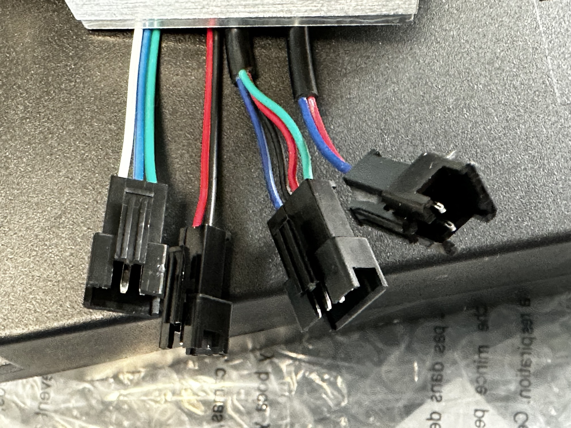
Lethal Lily control box wiring.
The cables are as follows:
Three-pin (green-blue-white) connector that goes to the SENSOR.
Four-pin (blue-black-red-green) goes to the HEAD.
Two-pin (black-red) that goes to … ? (probably lights)
Two-pin (blue-red) that goes to … ? (probably lights)
Inside the box is a small circuit board. I have not removed it to see what is on the bottom, but I suspect the processor is under the black blob.
Lethal Lily control circuit board.
POWER ADAPTER
The power adapter is odd — 5.9V DC, 3 amps.
Lethal Lily 5.9V 3A power adapter.
SENSOR
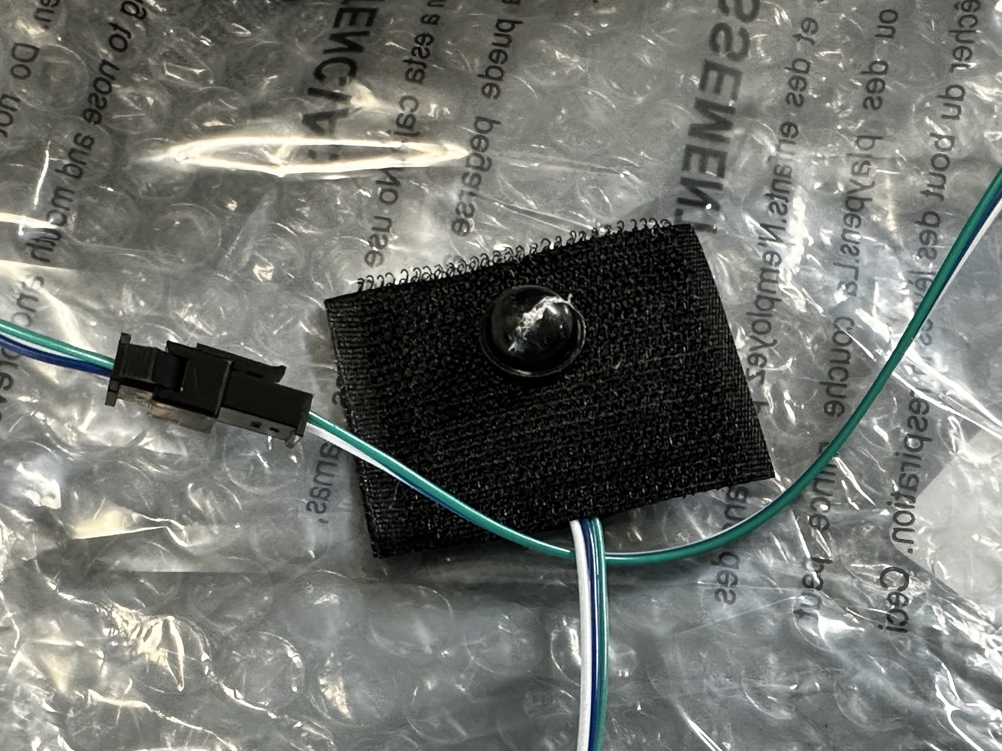
The SENSOR uses three wires, and I assume it is just a normal motion sensor. A PIR (passive infrared) motion sensor has three wires (voltage, ground, and the output).
Lethal Lily sensor.
HEAD
The head has a four-pin cable coming out of it near the metal shaft that is used to connect it to the frame.
Lethal Lily head cable.
How does it work?
I had hoped to find a bunch of different cables that would run to the head, each operating independent servos. Seeing only a four-wire connector made me wonder if they were sending commands (like I2C messages or something) or doing something else to address all eight (?) servos in the head.
The first thing I did was connect the power adapter and sensor, then hook the head cable up to a Saleae Logic Analyzer. I assumed the black wire to be ground, and the red wire to be power, so I looked at what was going on with the blue and green wires on the ends of the connector.
Lethal Lily head control hooked to a Saleae logic analyzer.
I triggered the sensor seven times (since my understanding is there are seven different patterns Lily can play). What I saw looked promising:
Lethal Lily Saleae capture.
The Green Wire
Above, Channel 0 was hooked to the green wire. This appears to be high except for a few pulses low at the start and end of the sequence, and another set of pulses low at the end.
As I checked the start and stop pulses for each sequence, I saw that they were different. The pulses would vary is width, making it look like it might be I2C or some similar protocol where LOW represents a 0 and HIGH represents a 1 (or vise versa). There are no clock pulses, so if this is encoding a number, it must be doing it based on predefined time, starting to count when it sees the pulse drop. That makes me think it could be normal serial data at some baud rate.
If that is the case, I can work out a sequence of numbers being sent by the green wire at the start and end of each sequence. The signal would drop to indicate the start of data (a “start bit”). Below, “D” is a down pulse, and “U” is back up. I can easily “see” eight in each of the start/end sequences:
UDDDDUUU / DDDUUUUD
DUDDUDUU / DDDUUUUD
UUDDDDUU / DDDUUUUD
DDUDUUDU / DDDUUUUD
UDUDDUDU / DDDUUUUD
DUUDUDDU / DDDUUUUD
UUUDDDDU / DDDUUUUD
Looking at the pulses this way shows a pattern. The end pulses are the same for each sequence. Using a serial decoder and and playing around with the baud rate until the bits decoded match where the pulses are, gives me something like this:
That is using a value of 550 baud. I have no idea if this is correct, but if so, it gives the following values for the start of each sequence. Note that the bits are being written least bit first (so, right to left) so UDDDDUUU becomes 11100001 in binary.
And at the end of each pattern, there is a 0x78 sent (as shown in the screen shot above):
78 - 11100001
I see a pattern! Each set of eight pulses is a 4-bit value, then the value with the bits inverted!
E1 - 11100001 - 1110 and 0001 (1)
D2 - 11010010 - 1101 and 0010 (2)
C3 - 11000011 - 1100 and 0011 (3)
B4 - 10110100 - 1011 and 0100 (4)
A5 - 10100101 - 1010 and 0101 (5)
96 - 10010110 - 1001 and 0110 (6)
87 - 10000111 - 1000 and 0111 (7)
The values go from 1 to 7 — matching the number of patterns the control box can perform. It looks like 0 is not used.
As for the end sequence of 78, that is the same pattern:
78 - 01111000 - 0111 and 1000 (8)
I do not know what these values instruct the head to do, but at least now I should be able to recreate sending those pulses out via an Arduino or something just by writing out a byte at 550 baud.
The Blue Wire
The data on the blue wire looks like pulses of different widths. My understanding is a servo position is set based on how wide of a pulse is sent. The head must be receiving these pulses and passing them to the different servos somehow. Speculation: Perhaps it sends eight pulses that go to servo 1, 2, 3, etc. and then restarts back at servo 1. (Me from the future: It does not…)
To figure out how many pulses there are for each of the seven sequences, I used the Saleae Logic Analyzer and highlighted a range of pulses. It showed me that each sequence has this many “rising edges” (where the pulse goes up):
85 pulses
87
75
87
100
96
79
(back to pattern 1) 84 … ?
Speculation: Seeing that the first pattern 1 reported 85 pulses in the Saleae Logic Analyzer, then the second one reported 84, tells me I may not have things set up properly with my Saleae.
This what not what I hoped to see. I expected. If there are eight servos, each number should be a multiple of eight. This clearly does not be the case. Perhaps the pulses can stop at any time (say, updating 8 servos, 8 servos, 8 servos, then just 3 for a total of 27 pulses)? I would still expect every pattern to end with pulses that set the head back to a default “off” state. Perhaps the head does that on its own when it receives the 0x78 “end” byte? Since the start bytes are different for each pattern, I suspect the head must need to know that for some purpose, as well. (Me from the future: This is foreshadowing…)
I also do not assume all servos are independently controlled. If each eye has it’s own left/right servo, one pulse could be sent to each eye so the move together. At some point I may have to take this thing apart and look inside.
Until then, let’s see what eight servos might control:
Head tilt forward and backwards.
Head tilt left and right.
Head turn left and right.
Left eye looks left and right.
Left eye looks up and down.
Right eye looks like and right.
Right eye looks up and down.
Eyelids blink.
Mouth open and close…if this is a servo?
Maybe this is why the wiki says nine?
And, if it is nine, but they tied the eyes together, it might really look like this to the control box signals:
Head tilt forward and backwards.
Head tilt left and right.
Head turn left and right.
Both eyes looks left and right.
Both eyes looks up and down.
Both eyelids blink.
Mouth open and close…if this is a servo?
That could mean that only seven pulses are needed in the sequence.
Before I can proceed, I need to hook up the head and see what all motions it does.
As a lifelong fan of Halloween, I certainly think we are living in a golden age when it comes to store-bought props and decorations. There are so many animated and light up props available each year at temporary stores (like Spirit) or, for some reason, home improvement stores like Home Depot and Lowes.
In 2023, Lethal Lily was introduced. This prop has eights servos to control its head – eyes move left, right, up and down. Eyelids blink. Mouth opens. And the head can turn and tilt forward and backwards (so it seems from the video).
Here was their press release, which contains a link to a video of Lily:
I am making this post in case someone else is considering hacking on these to control them via an Arduino, Raspberry Pi or some other keyword I would list here if I could think of it.
More to come… Leave a comment if you found this page, looking for this information.
In 1984, I was moved from Houston, Texas (where I grew up) to deep East Texas. I completed high school there, then moved to Lufkin, TX. That is where I lived when I started Sub-Etha Software with Terry Todd.
An interesting moment in my high school years was when a movie production company came to town to film something in San Augustine. My friend Jeremy (a drummer I played keyboards with) was from San Augustine. A group of us went down to audition to be extras in this movie.
Ned Beatty was in this thing! Apparently they turned the old downtown area in to “really old down town” by covering the streets with dirt and such.
I do not think any of us saw the movie when it was released in 1988. Just the other day, Jeremy contacted me asking if I knew what was involved in playing a PAL VHS tape. He had located a VHS copy of the movie — from another country. Here is a sub-titled trailer, though the movie is called “The Passage” in this trailer:
The Passage (1988)
When he sent me this, I went searching Ned Beatty’s IMDB page to look up more details. “The Passage” was not listed. I soon learned the movie was also called “After the Rain.” With that information, I was able to locate the IMDB entry and find a few other references to this film.
But, I cannot find any source to stream, rent or buy this film. Lost Media! At least in the USA.
I am posting this in case someone else is searching for it. (I did see one review on IMDB from someone who got to watch a premier of the film in Tyler, TX when it came out.)
Leave a comment if you end up hear after a search…
From my Park Hopping site, here is ten minutes of Insta360 VR 360 video.
I set the camera in various places using a Best360 tripod I purchased on Amazon. I set the camera to 8K 360 video mode and just clicked record. No manual settings – just automatic mode.
The only “editing” of the video was putting the clips together in Final Cut Pro’s 360 video editor, adding some transitions, and some overlay text. I did no color corrections or enhancements. These are the files exported out of the Insta360 desktop app and then brought into a Final Cut Pro 360 video timeline in 8K.
YouTube renders the video down to 4K, it seems, so I guess we can’t share 8K video on YouTube yet…
2024-04-26 – When I did this test, I recorded an 8K run, a 5.7K+ run, then 5.7K. I could not tell which video was which from looking at the info inside Insta360 Studio. I now think the #1 pass was in 5.7K+ mode. I will have to redo all of these ;-)
By request, here are comparison videos of the Insta360 X3 and Insta360 X4˘cameras recording in low light conditions. The recording was made at sunset, and the light level was low enough that the X4 displays the warning that it is too low for shooting in 8K.
But I did it anyway.
In the first test, I set the X3 to 360 mode and 5.7K. This allows reframing and exporting to HD. For the X4, I set it to 360 and 8K. This allows reframing and exporting to 4K. This obviously should make the X4 side have more detail, but what will it do to brightness of the video?
X3 5.7K versus X4 8K
X3 5.7K versus X4 5.7K+ (I think)
For the next test, I did two recordings with both cameras set to 360 5.7K+ (I think). In both cases, the reframed video is exported as HD. This was the mode the X4 tells you to use when recording in low light.
Test #1:
Test #2 in normal 5.7K mode (unless I have #1 and #2 mixed up):
Is one better than the other? You can certainly see alot of stabilization glitching going on at these low light levels.
To be continued…
I also repeated these tests at 24 fps (to see if that really does increase low light performance) and some other frame rates, but one of the files was incomplete from me hitting the button by mistake. I’ll go through the rest of my test clips, including some done in single lens mode, and create more comparison videos soon.
This should mean there were at least five versions of this manual. Does anyone have sources for other editions?
Also, the 1981 version was credited to Commodore International, Ltd. but the 1982 5th edition says Commodore Electronics, Ltd. What’s the story on the name change? Or was one the Commodore business from a different area of the world?
The reason behind this quest is to try to see how many versions of the type-in VIC-20 games were printed in these manuals. R.M. Smedley noticed that there were some minor differences in the Tank-V-UFO game listed in the 1981 version versus the 1982 version — specifically around lines 134-135.
I would like to find the other editions of this manual and try to type in all the program listings as accurately as possible so they can be compared.
I do not know how long this has been in the Insta360 mobile app, but when I was exporting an X4 clip today I noticed an option to enable “Dolby Vision Enhancement.”
Dolby Vision Enhanced
After transcoding, the details of the surface are significantly enhanced, enhancing the light and shadow effects and the sense of presence of the video, and presenting a more realistic color rendition of the real-life scenes.
I was unfamiliar with this, and looked it up on the wikipedia:
Does it really do anything beyond playing with colors? The Insta360 already has Color Plus and Clarity Plus to play with. I decided to do a quick test of the same Skylapse clip with and without Dolby Vision Enhancement:
Well, it’s bluer, at least. Now that I am aware of this option, I will do some more tests with other footage I have shot. Exporting from the mobile app does not offer the higher bitrate that the desktop Insta360 Studio has, but if this feature is in the desktop app, I could not locate it.
Here is a longer test, shot in single-lens mode:
More to come… Please leave a comment if you use this mode and tell us why.