Please read this tale with a sense of humor ;-) If you ended up on this page by searching for “Arduino account deactivated” or “Arduino wrong email/username or password” or similar, you can skip down to “Potential Solution” to see what you might be able to try…
Background
I created an Arduino account back in 2012 and popped in to the forum from time to time when I was working on a project. My last forum login was 2018. While I wasn’t using their forum often, I still had an Arduino UNO on my desk at work. I use it throughout the year to test 16-bit C code. I just had no reason to post about that mundane use in the forum, so I hadn’t been logging in.
In 2026, I got a new Arduino UNO R4 WiFi. When I tried to check out Arduino Cloud, I found my login did not work. Password recovery never sent a new password, and trying to sign up for a new account told me my username was already in use. Some quick searches revealed Arduino now deactivates accounts if you they are not being used often enough.
Support to the rescue! Well, not really…
I contacted support. They told me they could not reinstate my account. They said I needed to sign up with a new e-mail and create a new username. I pushed back on this. I’ve been using the same e-mail address since 1995 and see no reason to create a new one just for Arduino. Support merely pointed me to their Terms and Conditions:
10.5 Should User be inactive for twenty-four (24) months, Arduino may close their Account for inactivity. The posts made via the inactive Account will remain on the Forum and Project Hub for a period of five (5) years and will continue to identify User during such period via username, and after such five (5) year period such posts will become de-identified by deleting all Personal Data which may directly identify User.
Imagine not visiting Burger King for two years, then seeing some new marketing from their CEO that makes you want to go back and try the new Whopper… and the store tells you:
“Sorry, you haven’t been to Burger King in over 24 months, so we will not allow you back in unless you change your identify.”
Now, I’d like to point out that we agree to weird Terms and Conditions all the time. And companies will change their terms and conditions on us, all the time. We either accept the new terms or stop using the service. This seems fine. They can have whatever terms they wish and those of us that just click “I agree” without reading them can suffer the consequences — such as having your account deactivated.
If I had it to do all over, I would have just set a reminder to “Log in to Arduino” once a year. Problem solved ;-)
Can a company violate its own terms?
Remember, humor. If you are getting wound up by any of this, just remember it’s just some text on a random blog you stumbled into…
The 10.5 section I was pointed to says two things:
“Should User be inactive for twenty-four (24) months, Arduino may close their Account for inactivity.” Yep, they certainly did that. It has been over 24 months since I logged in. They are in compliance. Though, they say “may” so I wish they would have decided to not may for mine.
“The posts made via the inactive Account will remain on the Forum and Project Hub for a period of five (5) years and will continue to identify User during such period via username, and after such five (5) year period such posts will become de-identified by deleting all Personal Data which may directly identify User.” This one seems to be in violation, since 7+ years after my last login, all my information is still there – user profile, profile page, my posts, etc., all attributed to em.
I am bummed they honored #1 which was a “may”, but pleased they did not honor #2, which is a “will”.
Can a company be in violation of their own terms and conditions? Asking for a friend… ;-)
I went back and forth with Arduino Support a few times and eventually was transferred to someone in the “CX Education & Maker Support Team”, whatever that is. They finally gave me a solution, which might be a potential solution for you.
Potential Solution
If your Arduino Forum account is deactivated and you are unable to get back in using a password reset, try this:
Here is an interesting tidbit that I find very customer un-friendly.
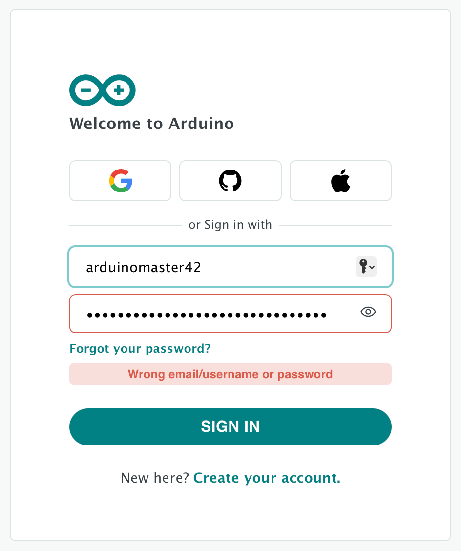
If you have not logged in to your Arduino account in 24 months, they “may” lock your account. If you try to log in after this happens, you will be told “Wrong email/username or password“.
Obviously you will try “Forgot your password.” That will give you the message:
Check your email, we just sent you a link to complete the reset of your password.
…but no e-mail ever shows up.
Some searching revealed they were purging accounts that had not been accessed. I tried to create a new account. As soon as I entered my exciting username, it told me:
This username is reserved: the account was recently deleted for inactivity.
And that led me to contacting their support.
Support says…
Unfortunately, support cannot reinstate old accounts. You have to create a new account using a new e-mail address and a new username. They pointed out it is in the terms of service:
And thus, my account I have had since I first signed up in 2012…
…is now frozen in time, and I have no access to it.
Terms for thee, but not for me?
I last logged in in 2018 – which is over five years ago. Since all my data is still there, and still identified via my username, it looks like Arduino may be in violation of its own terms of service. ;-) They definitely did the part they say they “may” do (close an account for inactivity) but the rest, not so much. That is really frustrating with an account I started 14 years ago.
And, to make matters worse, I have used the same e-mail address since 1995. For me to create a new e-mail address just for this one site and then not have access to all my messages, etc. from the past 14 years is … unfortunate.
Perhaps getting back into Arduino this week was a bad idea ;-)
In conclusion…
Go log in to your Arduino account if you want to keep it.
NOTE: This article was originally written two years ago, and meant to be part of a series. I never got around to writing Part 2, so I am just publishing this initial part by itself. If there is interest, I will continue the series. My Github actually shows the rest of the work I did for my “full” and “small” version of the driver code for this LCD.
Recently, my day job presented me an opportunity to play with a small 20×4 LCD display that hooked up via I2C. The module was an LCD2004. The 20 is the number of columns and the 04 is the number of rows. The LCD1602 would be a 16×2 display.
While I have found many “tutorials” about these displays, virtually all of them just teach you how to download a premade Arduino library and use library functions. Since I was going to be implementing code for an in-house project, and did not have room for a full library of functions I would not be using, I really needed to know how the device worked. Hopefully this article may help others who need (or just want) to do what I did.
LCD2004 / LCD1602 / etc.
These LCD modules use a parallel interface and requires eleven I/O pins. The pinout on the LCD looks like this:
A few of the pins are listed by different names based on whoever created the data sheet or hardware. On my LCD2004 module, pins 15 and 16 are listed as A and K, but I now know they are just power lines for the backlight.
If you have something like an Arduino with enough available I/O pins, you can wire the display up directly to pins. You should be able to hook up power (5V to VDD, Ground to VSS, and probably some power to the backlight and maybe something to control contrast), and then connect the eight data lines (D0-D7) to eight available digital I/O pins on the Arduino.
The LCD module has a simple set of instruction bytes. You set the I/O pins (HIGH and LOW, each to represent a bit in a byte), along with the RS (register select) and RW (read/write) pins, then you toggle the E (Enable) pin HIGH to tell the LCD it can read the I/O pins. After a moment, you toggle E back to LOW.
The data sheets give timing requirements for various instructions. If I read it correctly, it looks like the E pin needs to be active for a minimum of 150 nanoseconds for the LCD to read the pins.
Here is a very cool YouTube video by Ian Ward that shows how the LCD works without using a CPU. He uses just buttons and dip switches. I found it quite helpful in understanding how to read and write to the LCD.
If you don’t have 11 I/O pins, you need a different solution.
Ian Ward’s excellent LCD2004 video.
A few pins short of a strike…
If you do not have eleven I/O pins available, the LCD can operate in a 4-bit mode, needing only four pins for data. You send the upper four bits of a byte using the E toggle, followed by the lower 4-bits of the byte. This is obviously twice as slow, but allows the part to be used when I/O pins are limited.
If you don’t have 7 I/O pins, you need a different solution.
PCF8574: I2C to I/O
If you do not have seven I/O pins available, you can use the PCF8574 chip. This chip acts as an I2C to I/O pin interface. You write a byte to the chip and it will toggle the eight I/O pins based on the bits in the byte. Send a zero, and all pins are set LOW. Send a 255 (0xff) and all pins are set HIGH.
Using a chip like this, you can now use the 2-wire I2C interface to communicate with the LCD module–provided it is wired up and configured to operate in 4-bit mode (four pins for data, three pins for RS, RW and E, and the spare pin can be used to toggle the backlight on and off).
Low-cost LCD controller boards are made that contain this chip and have pins for hooking up to I2C, and other pins for plugging directly to the LCD module. For just a few dollars you can buy an LCD module already soldered on to the PCF8574 board and just hook it up to 5V, Ground, I2C Data and I2C Clock and start talking to it.
If you know how.
I did not know how, so I thought I’d document what I have learned so far.
What I have learned so far.
The PCF8574 modules I have all seem to be wired the same. There is a row of 16-pins that aligns with the 16 pins of the LCD module.
PCF8574 module.
One LCD I have just had the board soldered directly on to the LCD.
LCD2004 with the PCD8574 module soldered on.
Another kit came with separate boards and modules, requiring me to do the soldering since the LCD did not have a header attached.
PCF8574 module and LCD1602, soldering required.
If you are going to experiment with these, just get one that’s already soldered together or make sure the LCD has a header that the board can plug in to. At least if you are like me. My soldering skills are … not optimal.
The eight I/O pins of the PCF modules I have are connected to the LCD pins as follows:
1 - to RS
2 - to RW
3 - to E
4 - to Backlight On/Off
5 - D4
6 - D5
7 - D6
8 - D7
If I were to send an I2C byte to this module with a value of 8 (that would be bit 3 set, with bits numbers 0 to 7), that would toggle the LCD backlight on. Sending a 0 would turn it off.
That was the first thing I was able to do. Here is an Arduino sketch that will toggle that pin on and off, making the backlight blink:
// PCF8574 connected to LCD2004/LCD1602/etc.
#include <Wire.h>

void setup() {
  // put your setup code here, to run once:
  Wire.begin ();
}

void loop() {
  // put your main code here, to run repeatedly:
  Wire.beginTransmission (39); // I2C address
  Wire.write (8); // Backlight on
  Wire.endTransmission ();

  delay (500);

  Wire.beginTransmission (39); // I2C address
  Wire.write (0); // Backlight off
  Wire.endTransmission ();

  delay (500);
}
Once I understood which bit went to which LCD pin, I could then start figuring out how to talk to the LCD.
One of the first things I did was create some #defines representing each bit:
We’ll use this later when building our own bytes to send out.
Here is a datasheet for the LCD2004 module. Communicating with an LCD1602 is identical except for how many lines you have and where they exist in screen memory:
I actually started with an LCD1602 datasheet and had it all working before I understood what “1602” meant a different sized display than whatI had ;-)
Sending a byte
As you can see from the above sample code, to send an I2C byte on the Arduino, you have to include the Wire library (for I2C) and initialize it in Setup:
#include <Wire.h>

void setup() {
  // put your setup code here, to run once:
  Wire.begin ();
}
Then you use a few lines of code to write the byte out to the I2C address of the PCF8574 module. The address is 39 by default, but there are solder pads on these boards that let you change it to a few other addresses.
Communicating with the LCD module requires a few more steps. First, you have to figure out which pins you want set on the LCD, then you write out a byte that represents them. The “E” pin must be set (1) to tell the LCD to look at the data pins.
After a tiny pause, you write out the value again but with the E pin bit unset (0).
That’s all there is to it! The rest is just understanding what pins you need to set for what command.
Instructions versus Data
The LCD module uses a Register Select pin (RS) to tell it if the 8-bits of I/O represents an Instruction, or Data.
Instruction – If you set the 8 I/O pins and have RS off (0) then toggle the Enable pin on and off, the LCD receives those 8 I/O pins as an Instruction.
Data – If you set the 8 I/O pins and have RS on (1) then toggle the Enable pin on and off, the LCD received those 8 I/O pins as a Data byte.
Reading and Writing
In addition to sending Instructions or Data to the LCD, you can also read Data back. This tutorial will not cover that, but it’s basically the same process except you set the Read/Write pin to 1 and then pulse the E pin high/low and then you can read the pins that will be set by the LCD.
Initialize the LCD to 4-bit mode
Since only 4 of the PCF8574 I/O pins are used for data, the first thing that must be done is to initialize the LCD module to 4-bit mode. This is done by using the Function Set instruction.
Function set is described as the following:
RS  RW  DB7 DB6 DB5 DB4 DB3 DB2 DB1 DB0
--- --- --- --- --- --- --- --- --- ---
0   0   0   0   1   DL  N   F   x   x
Above, RS is the Register Select pin, RW is the Read/Write pin, and DB7-DB0 are the eight I/O pins. For Function Set, pins DB7-DB5 are “001” representing the Function Select instruction. After that, the pins are used for settings of Function Select:
DB4 is Data Length select bit. (DL)
DB3 is Number of Lines select bit
DB2 is Font select bit
When we are using the PCF8574 module, it ONLY gives us access to DB7-DB4, so it is very smart that they chose to make the DL setting one of those four bits. We have no way to access the pins for N or F until we toggle the LCD in to 4-bit data length mode.
If we were using all 8 I/O pins, we’d set them like this to go in to 4-bit mode:
That sequence will initialize the LCD so we can send it commands. After that, we can use Function Set to change it to 4-bit mode (DB4 as 0 for 4-bit mode):
If we used all 8 I/O pins directly, we could also set Font and Number of lines at the same time after the three initializing writes. BUT, since we are using the PCD8547 and only have access to the top four bits (DB7-DB4), we must put the LCD in to 4-bit mode first. More details on how we use that in a moment.
If I wanted to initialize the LCD, I would just need to translate the I/O pins into the bits of a PCF8574 byte. For the first three initialization writes, it would look like this:
ABove, you see only need to pass in the bit pattern for DB7 DB6 DB5 DB4. This routine will set the Backlight Bit (it doesn’t have to, but I didn’t want the screen to blank out when sending these instructions), and then write the byte out with the E pin set, pause, then write it out again with E off.
Thus, my initialization can now look like this:
// Initialize all pins off and give it time to settle.
Wire.beginTransmission(PCF8574_ADDRESS);
Wire.write(0x0);
Wire.endTransmission();

delayMicroseconds(50000);

// [7  6  5  4  3  2  1  0 ]
// [D7 D6 D5 D4 BL -E RW RS]
LCDWriteInstructionNibble(0b0011);
delay(5); // min 4.1 ms

LCDWriteInstructionNibble(0b0011);
delayMicroseconds(110); // min 100 us

LCDWriteInstructionNibble(0b0011);
delayMicroseconds(110); // min 100 us

// Set interface to 4-bit mode.
LCDWriteInstructionNibble(0b0010);
That looks much more obvious, and reduces the amount of lines we need to look at since the function will do the two writes (E on, E off) for us.
Sending 8-bits in a 4-bit world
Now that the LCD is in 4-bit mode, it will expect those four I/O pins set twice — the first time for the upper 4-bits of a byte, and then the second time for the lower 4-bits. We could, of course, do this manually as well by figuring all this out and building the raw bytes outselves.
But that makes my head hurt and is too much work.
Instead, I created a second function that will send an 8-bit value 4-bits at a time:
You’ll notice I pass in the Register Select bit, which can either be 0 (for an Instruction) or 1 (for data). That’s jumping ahead a bit, but it makes sense later.
I can then pass in a full instruction, like sending Function set to include the bits I couldn’t set during initialization when the LCD was in 8-bit mode and I didn’t have access to DB3-DB0. My LCDInit() routine set the LCD to 4-bit mode, and then uses this to send out the rest of the initialization:
// Function Set
// [0  0  1  DL N  F  0  0 ]
// DL: 1=8-Bit, 0=4-Bit
//  N: 1=2 Line, 0=1 Line
//  F: 1=5x10, 0=5x8
//             [--001DNF00]
LCDWriteByte(0, 0b00101000); // RS=0, Function Set

// Display On
// [0  0  0  0  1  D  C  B ]
// D: Display
// C: Cursor
// B: Blink
//             [--00001DCB]
LCDWriteByte(0, 0b00001100); // RS=0, Display On

// Display Clear
// [0  0  0  0  0  0  0  1 ]
LCDWriteByte(0, 0b00000001);
delayMicroseconds(3);  // 1.18ms - 2.16ms

// Entry Mode Set
// [0  0  0  0  0  1  ID S ]
// ID: 1=Increment, 0=Decrement
//  S: 1=Shift based on ID (1=Left, 0=Right)
//             [--000001IS]
LCDWriteByte(0, 0b00000110);
To make things even more clear, I then created a wrapper function for writing an Instruction that has RS at 0, and another for writing Data that has RS at 1:
// Entry Mode Set // [0 0 0 0 0 1 ID S ] // ID: 1=Increment, 0=Decrement // S: 1=Shift based on ID (1=Left, 0=Right) // [--000001IS] LCDWriteInstructionByte(0b00000110);
The Display Clear instruction is 00000001. There are no other bits that need to be set, so I can clear the screen by doing “LCDWriteInstructionByte (0b00000001)” or simply “LCDWriteInstructionByte(1)”;
Ultimately, I’d probably create #defines for the different instructions, and the settable bits inside of them, allowing me to build a byte like this:
FUNCTION_SET would represent the bit pattern 0b00100000, and the DL_BIT would be BIT(4), N_BIT would be BIT(3) and F_BIT would be BIT(2). Fleshing out all of those defines and then making wrapper functions would be trivial.
But in my case, I only needed a few, so if you wanted to make something that did that, you could:
This type of thing can allow your code to spiral out of control as you create functions to set bits in things like “Display On/Off Control” and then write wrapper functions like “LCDDisplayON()”, “LCDBlinkOn()” and so on.
But we won’t be going there. I’m just showing you the basic framework.
Now what?
With the basic steps to Initialize to 4-Bit Mode, then send out commands, the rest is pretty simple. If you want to write out bytes to be displayed on the screen, you just write out a byte with the Register Select bit set (for Data, instead of Instruction). The byte appears at whatever location the LCD has for the cursor position. Simple!
At the very least, you need a Clear Screen function:
The last thing I implemented was a thing that sets the X/Y position of where text will go. This is tricky because the display doesn’t match the memory inside the screen. Internally my LCD2004 just has a buffer of screen memory that maps to the LCD somehow.
The LCD data is not organized as multiple lines of 20 characters (or 16). Instead, it is just a buffer of screen memory that is mapped to the display. In the case of the LCD2004, the screen is basically 128 bytes of memory, with the FIRST line being bytes 0-19, the SECOND line being bytes 64-83, the THIRD line being bytes 20-39, and the FOURTH line being bytes 84-103.
If you were to start at memory offset 0 (top left of the display) and write 80 bytes of data (thinking you’d get 20, 20, 20 and 20 bytes on the display), that wouldn’t happen ;-) You’d see some of your data did not show up since it was writing out in the memory that is not mapped in to the display. (You can also use that memory for data storage, but I did not implement any READ routines in this code — yet.)
If you actually did start at offset 0 (the first byte of screen memory) and wrote a series of characters from 32 (space) to 127 (whatever that is), it would look like this:
Above, you can see the first line continues on line #3, and then after the end of line 3 (…EFG” we don’t see any characters until we get to the apostrophe which displays on line 2. Behind the scenes, memory looks like this:
All you need to know is that the visible screen doesn’t match LCD memory, so when creating a “set cursor position” that translates X and Y to an offset of memory, it has to have a lookup table, like this one:
You will see I created a function that sends the “Set Offset” instruction (memory location 0 to 127, I think) and then a “Set X/Y” function that translates columns and rows to an offset.
With all that said, here are the routines I cam up with. Check my GitHub for the latest versions:
The LCDTest.ino program also demonstrates how you can easily send an Instruction to load character data, and then send that data using the LCDWriteData functions.
I plan to revisit this with more details on how all that works, but wanted to share what I had so far.
Prototype “Sir Sound” sound module for the CoCo (or anything with a serial port, actually).
So … many … wires.
At the time, I was hoping to find some kind of Arduino emulator so I could write and test code without hooking up hardware. I found nothing.
But that seems to have changed. I just learned about Wokwi which allows one to “simulate IoT projects in your browser.” In a nutshell, it’s a website that has a code editor (which appears to be Microsoft Visual Studio Code), compiler, and virtual target hardware like Arduino and ESP32 devices. It even supports some add-on hardware, like buttons, LCD displays, LEDs and more.
Here’s a project someone made that simulates an Arduino hooked to a numeric keypad and LCD display:
And you can build and run it right there!
There is a library of devices that are supported, and you can add them to your project and wire them up to the computer’s I/O pins. For example, as I write this blog post, I opened up a starter project that is an Arduino and a two-line LCD display. I then added a pushbutton to it.
I could then move the button to where I wanted it, then click on the connectors and draw wire lines between it and I/O pins on the Arduino. By hooking one side to an I/O pin, and the other to ground, I could then modify the program to read that button and, for this example, increment a counter while the button is being held done.
It’s just that easy! I had no idea!
The files can be downloaded and used on real hardware, or you can make an account and log back in to continue working on them. (It has an unusual way to log in — it sends you an e-mail and you click a link to log in, rather than having a username and password. This seems to mean I cannot log in from any system that I don’t have my e-mail account configured on, but I do see options for using a Google or Github login.)
For a future project, I need to make use of remote triggers. These could be motion sensors, beam sensors, pressure mats, etc.
The ZigBee standard seems to be the way to go since I can find cheap consumer motion sensors that run on batteries. There also seems to be ZigBee repeaters, which allow giving the distance I need simply by plugging them in from place to place to create a mesh network.
XBee might be another option, if cheap motion sensors and repeaters are also available.
The goal is to have a central location be able to read the motion sensor status for many sensors, that could be spread out beyond walls hundreds of feet away.
Any pointers to where I might get started would be appreciated. Ideally I’d drive this all by a low-cost Arduino since the device will be used in an area where power might not be stable (and I wouldn’t want to corrupt the Linux file system on a Raspberry Pi).
…but if I convert the printf() and run the same code on an Arduino:
void setup() {
  // put your setup code here, to run once:
  Serial.begin(9600);

    uint16_t    val1;
    uint16_t    val2;
    uint32_t    result;

    val1 = 40000;
    val2 = 50000;

    result = val1 + val2;

    //printf ("%u + %u = %u\n", val1, val2, result);
    Serial.print(val1);
    Serial.print(" + ");
    Serial.print(val2);
    Serial.print(" = ");
    Serial.println(result);
}

void loop() {
  // put your main code here, to run repeatedly:

}
This gives me:
40000 + 50000 = 24464
…and this was the source of a bug I introduced and fixed at my day job recently.
Tha’s wrong, int’it?
I tend to write alot of code using the GCC compiler since I can work out and test the logic much quicker than repeatedly building and uploading to our target hardware. Because of that, I had “fully working” code that was incorrect for our 16-bit PIC24 processor.
In this case, the addition of “val1 + val2” is being done using native integer types. On the PC, those are 32-bit values. On the PIC24 (and Arduino, shown above), they are 16-bit values.
A 16-bit value can represent 65536 values in the range of 0-65535. If you were to have a value of 65535 and add 1 to it, on a 16-bit variable it would roll over and the result would be 0. In my example, 40000 + 50000 was rolling over 65535 and producing 24464 (which is 90000 – 65536).
You can see this happen using the Windows calculator. By default, it uses DWORD (double word – 32-bit) values. You can do the addition just fine:
You see that 40,000 + 50,000 results in 90,000, which is 0x15F90 in hex. That 0x1xxxx at the start is the rollover. If you switch the calculator in to WORD mode you see it gets truncated and the 0x1xxxx at the start goes away, leaving the 16-bit result:
Can we fix it?
The solution is very simple. In C, any time there is addition which might result in a value larger than the native int type (if you know it), you simply cast the two values being added to a larger data type, such as a 32-bit uint32_t:
void setup() {
  // put your setup code here, to run once:
  Serial.begin(9600);

    uint16_t    val1;
    uint16_t    val2;
    uint32_t    result;

    val1 = 40000;
    val2 = 50000;

    // Without casting (native int types):
    result = val1 + val2;

    //printf ("%u + %u = %u\n", val1, val2, result);
    Serial.print(val1);
    Serial.print(" + ");
    Serial.print(val2);
    Serial.print(" = ");
    Serial.println(result);

    // Wish casting:
    result = (uint32_t)val1 + (uint32_t)val2;

    Serial.print(val1);
    Serial.print(" + ");
    Serial.print(val2);
    Serial.print(" = ");
    Serial.println(result);
}

void loop() {
  // put your main code here, to run repeatedly:

}
Above, I added a second block of code that does the same add, but casting each of the val1 and val2 variables to 32-bit values. This ensures they will not roll over since even the max values of 65535 + 65535 will fit in a 32-bit variable.
The result:
40000 + 50000 = 24464
40000 + 50000 = 90000
Since I know adding any two 16-bit values can be larger than what a 16-bit value can hold (i.e., “1 + 1” is fine, as is “65000 + 535”, but larger values present a rollover problem), it is good practice to just always cast upwards. That way, the code works as intended, whether the native int of the compiler is 16-bits or 32-bits.
As my introduction of this bug “yet again” shows, it is a hard habit to get in to.
In Arduino, instead of being able to use things like printf() and puchar(), console output is done by using the Serial library routines. It provides functions such as:
Serial.print();
Serial.println();
Serial.write();
These do not handle any character formatting like printf() does, but they can print strings, characters or numeric values in different formats. Where you might do something like:
int answer = 42;
printf("The answer is %d\r\n", answer);
…the Arduino version would need to be:
int answer = 42;
Serial.print("This answer is ");
Serial.print(answer);
Serial.println();
To handle printf-style formatting, you can us sprintf() to write the formatted string to a buffer, then use Serial.print() to output that. I found this blog post describing it.
I recently began porting my Arduino Telnet routine over to standard C to use on some PIC24 hardware I have at work. I decided I should revisit my Telnet code and try to make it portable, so the code could be built for Arduino or standard C. This would mean abstracting all console output, since printf() is not used on the Arduino.
I quickly came up with these Arduino-named macros I could use on C:
#include <stdio.h>
#include <stdlib.h>

#define SERIAL_PRINT(s)     printf(s)
#define SERIAL_PRINTLN(s)   printf(s"\r\n")
#define SERIAL_WRITE(c)     putchar(c)

int main()
{
    SERIAL_PRINT("1. This is a line");
    SERIAL_PRINTLN();
    SERIAL_PRINTLN();

    SERIAL_PRINTLN("2. This is a second line.");

    SERIAL_PRINT("3. This is a character:");
    SERIAL_WRITE('x');
    SERIAL_PRINTLN();

    SERIAL_PRINTLN("done.");

    return EXIT_SUCCESS;
}
Ignoring the Serial.begin() setup code that Arduino requires, this would let me replace console output in the program with these macros. For C, it would use the macros as defined above. For Arduino, it would be something like…
But, if I wanted to keep code portable, C can certainly do three separate printf()s to do the same output as Arduino, so we code for the lowest level output.
One thing I don’t do, yet, is handle porting things like:
Serial.print(val, HEX);
On Arduino, that outputs the val variable in HEX. I’m not quite sure how I’d make a portable macro for that, unless I did something like:
I expect to add more macros as-needed when I port code over. This may be less efficient, but it’s easier to make Arduino-style console output code work on C than the other way around.
Years ago, I cloned the Arduino IDE “bit” macros for use in a GCC program (for testing generic Arduino code on a different system). I dug them out recently for a work project, and decided to share them here. Maybe they will be useful to someone else. (And apologies for WordPress clobbering the ampersand and turning it to HTML. When I edit and view it, it looks good, then WordPress “helps” — even though I am using a Syntax Highlighter plugin specifically for code examples.)
#ifndef BITMACROS_H
#define BITMACROS_H
// Bit macros, based on Arduino standard.
// https://www.arduino.cc/reference/en/language/functions/bits-and-bytes/bit/
//
// x: the numeric variable to which to write.
// n: which bit of the number to write, starting at 0 for the least-significant (rightmost) bit.
// b: the value to write to the bit (0 or 1).
#define bit(n)              (1 << (n))
#define bitSet(x, n)        ((x) |= bit(n))
#define bitClear(x, n)      ((x) &= ~bit(n))
#define bitRead(x, n)       (((x) & bit(n)) !=0 )
#define bitWrite(x, n, b)   ((b) ? bitSet((x), (n)) : bitClear((x), (n)))
/* Verification tests:
bool showBits (uint32_t value, unsigned int bits)
{
    bool status;
    //printf ("showBits (%u, %u)\n", value, bits);
    if ((bits == 0) || (bits > sizeof(value)*8))
    {
        status = false;
    }
    else
    {
        // Must use signed to check against 0.
        for (int bit = (bits-1); bit >= 0; bit--)
        {
            printf ("%u", bitRead(value, bit));
        }
        printf ("\n");
    }
    return status;
}
int main()
{
    unsigned int value;
    // Test bit()
    for (unsigned int bit = 0; bit < 8; bit++)
    {
        printf ("bit(%u) = %u\n", bit, bit(bit));
    }
    printf ("\n");
    // Test bitSet()
    for (unsigned int bit = 0; bit < 8; bit++)
    {
        value = 0;
        printf ("bitSet(%u, %u) = ", value, bit);
        bitSet(value, bit);
        showBits (value, 8);
    }
    printf ("\n");
    // Test bitClear()
    for (unsigned int bit = 0; bit < 8; bit++)
    {
        value = 0xff;
        printf ("bitClear(%u, %u) = ", value, bit);
        bitClear (value, bit);
        showBits (value, 8);
    }
    printf ("\n");
    // Test bitRead()
    value = 0b10101111;
    showBits (value, 8);
    for (unsigned int bit = 0; bit < 8; bit++)
    {
        printf ("bitRead(%u, %u) = %u\n", value, bit, bitRead (value, bit));
    }
    printf ("\n");
    // Test bitWrite - 1
    value = 0x00;
    showBits (value, 8);
    for (unsigned int bit = 0; bit < 8; bit++)
    {
        printf ("bitWrite(%u, %u, 1) = ", value, bit);
        bitWrite (value, bit, 1);
        showBits (value, 8);
    }
    // Test bitWrite - 0
    showBits (value, 8);
    for (unsigned int bit = 0; bit < 8; bit++)
    {
        printf ("bitWrite(%u, %u, 0) = ", value, bit);
        bitWrite (value, bit, 0);
        showBits (value, 8);
    }
    printf ("\n");
    return EXIT_SUCCESS;
}
*/
#endif // BITMACROS_H
// End of BitMacros.h
Things have been real busy lately at Sub-Etha Galactic Headquarters… Here are some updates:
CoCoWiFi
The CoCoWiFi has been tested on the bitbanger serial port and things seem to work just fine.
On the RS-232 Pak, a modification was needed to make the pak actually receive data (forcing the carrier detect signal). This has been done by an easy soldering mod to the DB9 connector. The downside is that it does not provide true CD, and there is no support for hardware flow control or DTR to drop calls. For just a bit more, there are RS232-to-TTL adapters that provide hardware flow control, which might help for doing high speed transfers. However, the lack of carrier detect and DTR means they won’t work with a BBS like they should
Thanks to David Chesek, new RS232-to-TTL adapters were located that include all the signals. These would be the best choice for running with an RS-232 Pak. I have two different types of adapters, but have only done some initial testing. I was unsuccessful getting the first adapter to work. I plan to test the second version this week.
I hope to have a hardware announcement to make before the CoCoFEST!
SirSound
I learned much while working on CoCoWiFi, so I returned to work on the previously “announced” SirSound project. I got everything wired up properly and was able to write a BASIC program to make it play tones. I also worked with John Strong and migrated the prototype over to an Arduino Nano (matching the original Arduino sound player board he sent me last year).
The next phases is to figure out the various modes that sound module will run in. I have proposed:
Direct. This mode just passes bytes to the sound chip, the same way you might do with a POKE command if it was a memory-mapped chip. BASIC is very slow at ANDing and ORing bits to make the messages, which is how my test program works, but this could be heavily optimized. This mode is mostly here to allow someone to port over code that was written for one of the other platforms that use an on-board SN76489 sound chip, though some of the bit-blasting players would probably not work as well over slow serial.
PLAY. This is the BASIC mode, that will simulate the PLAY command. You will be able to send a string of notes to SirSound and play them just as easy as in EXTENDED COLOR BASIC. There are a few things that have to be adapted, like support for the multiple channels of audio, and sub-strings. Last year, it was suggested to look at the MSX computer’s PLAY command for examples of how Microsoft did this very thing. I may follow that syntax. MSX also ads a PLAY() function that can tell is background audio is in progress, and we will be able to achieve the same results using the Printer Read/CD signal on the bitbanger port. I plan to also add some sequencing extensions so repeating music loops don’t have to be sent over and over again.
Optimized. This mode would be for assembly programs, and would pack data into 8-bit values rather than longer ASCII strings.
Interactive. I am planning on having a shell/command-line interface (CLI) available which could be accessed. It would be used for testing the device without needing to write a BASIC program.
Now working without the crystal. This is using a Teensy and one of the pins to generate a 4mhz signal. I will post a video in coming days, hopefully, as soon as I have some CoCo BASIC code talking to it.
The green and black wires running off of it wold go to a headphone jack that the cassette cable could plug in to so you could feed Sound back to the CoCo without needing to use an external speaker. AUDIO ON!