At the 1994 Atlanta CoCoFest, the following vendors were present:
Booth 20 was unoccupied, as the vendor did not make it. They did leave a stack of flyers explaining their absence. You can read the text of that flyer in the previous post.
Who was Klystronics? Beyond those that knew about it in 1994, the backstory was explained in my CoCoFest Chronicles book which you can download for free at the Color Computer archive.
First, my fest report text file (included in the book) alluded to it in the opening:
NOTE: Any discrepancies between what is contained in this report and what is real is merelycoincidental. This includes, but is not limited to, names, locations, events, and inside jokes(like klystrons).
– Allen Huffman’s 1994 Atlanta CoCoFest report text file
That report also mentioned the booth:
Klystronics — Another new vendor. This group was offering a large supply of “gently used” klystrons, complete with manuals. The minimal water damage their inventory had didn’t seem to effect operation, though the yellow discoloration made them no longer match the CoCo’s case.
– Allen Huffman’s 1994 Atlanta CoCoFest report text file
…but the full backstory was not explained until the book itself came out a few years later. From the book:
MORE BEHIND THE SCENES
The Story About Klystronics
One of the more interesting tales I get to tale is that of the “mysterious” vendor, Klystronics. They were listed in the Fest booklet, and even had a table which was empty except for some flyers and an empty business card holder. To the casual observer (i.e. someone who fell for it) it would appear they just didn’t make it to the show. To the less casual observer, one might have found some of the information on the flyer a bit curious.
Klystronics was a practical joke played for the benefit of one individual, Nick Johnson. At the time, Nick was hanging out on the GEnie online service (thanks to its then-outstanding Star*Services which offered unlimited non-prime access for about five dollars per month). Nick had a macro he would use far too often while in chat sessions which said “PLEASE DO NOT URINATE ON THE KLYSTRON.” Terry Todd and myself found this quite annoying.
At some point, our friend Bob Rutherford got together with us and we came up with the idea of Klystronics. Once the name was created, the joke fell into place. We acquired a booth, printed flyers (using a font I had never used for any Sub-Etha literature), and purchased a business card holder.
At the show, Nick wandered over and said “hey, did you guys know there is a company here called Klystronics?” or something to that effect. We held in laughter. He most likely was suspicious but if so he played along pretty well. The flyer had some meaningless babble about CoCo compatible Klystrons, but embedded in the words were numbers enclosed in brackets. If you put the letter next to the numbers together in numerical order you would decode the hidden message which basically clued one in to the fact that this was just a joke. At first Nick suspected something far more clever for the origin of the numbers, but towards the end of the show I do believe he figured it out. I am not quite sure if we ever told him officially that it really was us.
A few others were in on this joke, most notable Colin McKay. After the Fest, Colin played up the existence of Klystronics on the internet CoCo mailing list after someone wondered just who they were. Even Mike Knudsen chimed in observing that certainly they had nothing to do with the “klystron” tubes he was familiar with! He certainly was right. I have in my possession (thanks to Mike’s archives) a copy of the Klystronics message thread and I must say — it really makes me proud seeing how well this went over.
The following Fest, we planned to do more including having Bob Rutherford build a rather amazing device to attach to a CoCo. We never quire followed through, but Klystronics lived on in my Fest report — even though there was no booth nor mention of them in the official Fest booklet.
And now you know … the rest of the story. Maybe the comment about “water damage” will make a bit more sense.
Or, more likely, it will not.
I decided to post the original Kystronics flyer text on April 1, 2026. This was more involved than I expected. First, the raw text file seemed to use some embedded formatting codes. I could not remember what created them:
.pl1
.lm0
.ll137
.nf
This led me to trying to figure out how to export the document in a formatted version to match what I did back in 1994. I was using the text editor VED under OS-9 at the time, and suspected maybe I was using the companion VPT text formatted. After figuring out how to run it off my old OS-9 hard drive image in an emulator, I learned it did not like these codes.
Eventually, I just decided to feed it into A.I. (Copilot) and let it do it for me. It presented me with an ASCII version of document, correctly figuring out what codes mean blank lines, and what codes meant centered lines. BUT, it was 137 columns wide.
What? That wouldn’t even fit if I printed in landscape mode, which wasn’t even a thing on that printer back then.
A bit more research revealed I likely printed this on my Tandy DMP-132 printer in condensed mode, which would indeed allow 137 characters per line with a bit of margin on each side.
This led me to just simulating it by using a condensed dot matrix font and turning the text into a PDF.
That’s close-ish.
Some things seem obvious now…
As I pointed out, I tried to use a font Sub-Etha Software didn’t use for printing flyers, and change things up so it was not immediately obvious I created this. For instance, it spells “disc” with a C and I never did that. It also uses “Coco” without the second C capitalized. But, as I look at it now, I see a few things that would have tipped folks off.
First, back then, I typed DOS as “Dos” as if it was a word. So did Klystronics. (And other folks of that era, but still, a hint.)
Also, “S.E.S.” Dos and “B.H.” Dos? I’ve never heard of any RS-DOS replacements with those initials, but there were two companies at the fest that had matching initials.
I also misspelled separately the same way I’d be misspelling it today if it wasn’t for auto-correct. And so did Klystronics. My Fest reports were full of that misspelling as well as mixing of where/were.
Bored member? “lol”. That misspelling was intentional.
The document also has some things that could further tip off the joke.
16K RAM, but also supporting the Hi-Res Joystick Interface? Seems unlikely.
Color Computer 2 but NOT Color Computer 1? Why would that be?
Also, the name “Graham Cain” alluded to the two individuals behind it. One may be obvious, the other not at all.
But … the biggest tip was that there is also an encoded message hidden in this document. Look at the full text and see if you can decode it. That was the actual reveal.
HELLO! We are[14] sorry that we were unable to personally attend this[1] year’s CocoFest. We had some commercial accounts we needed to attend to and thus were unavailable. We hope to see you[9] next year at the 1995 Chicago CocoFest or at the upcoming Klystrone Con[4] ’95 in Aneheim.
WHAT IS KLYSTRONICS?
Klystronics, Inc. is an independent organization dealing in the sale and service of both new and used Klystrones.
WHAT IS A KLYSTRONE?
Klystronics, Inc. is an independent organization dealing in the sale and service of both new and used Klystrones.
WHY IS KLYSTRONICS AT A COCOFEST?
One of our[11] bored members, Graham Cain, got his start in the electronics field with a[3] TRS-80 Color Computer which was part of an in-home study course. His projects led him into P.C. interfacing and, along with other business partners, the formation of Klystronics in 1989. Most of the projects were industrial in nature and involved the usage of Klystrone units with commercial grade P.C. components, but Graham, remembering his roots with the Coco, used his knowledge and spare time to create a Coco Klystrone interface. Thus, Klystronics offers it’s services to both industrial users and Color Computer users.
HOW CAN I ORDER A KLYSTRONE FROM KLYSTRONICS?
Since we are[6] unable to take orders personally, you[13] can mail in your order or use our toll free 1-800 telephone ordering service. We accept personal and business checks, credit cards (Visa, MasterCard, Diner’s Club, Discover[10]), money orders, international postage, and C.O.D.s.
KLYSTRONE SYSTEM REQUIREMENTS:
o Color Computer 2 or 3 o Y-Cable of Multi-Pak Interface o Cassette Cable (if[8] sound desired) o Floppy Disc Drive (S.E.S./B.H.[5] Dos)
o 16K of R.A.M. or greater o Hi-Res Joystick Interface o Color Monitor recommended o OS-9 Drivers Sold Seperately
TECHNICAL SUPPORT FOR KLYSTRONE QUESTIONS:
Support is[2] provided 24 hours a day via long distance phone calls, or use our free computer bulletin board service (300-1200 baud). We may also be contacted via Prodigy, though response time may be slow. We are not responsible[7] if the message[12] is lost.
CONTACT
Please use the latest address and phone information as listed on our business cards.
FEST SPECIAL[15]!!!!! USED KLYSTRONES (SLIGHT WATER DAMAGE) 37% OFF!!!!!
In part 5, I presented an update to the “PRINT can move the cursor” hack which would turn that off when you were typing from outside a running program. It did this by checking a Color BASIC “variable” that contained the current line being processed. When the program is not running, that value is set to 65535 (&HFFFF in hex). My simple check should have been enough to skip processing the special characters when in this direct mode:
* Do this only if NOT in Direct mode. Problem: After a BREAK, CURLIN
* has not been updated yet, so the very first line you type will be
* processing the special characters. Lines after that will not. Trying
* to find a different way to detect this.
pshs    a           save A
lda     CURLIN      GET CURRENT LINE NUMBER (CURLIN)
inca                TEST FOR DIRECT MODE
puls    a           restore A
beq     continue    if 0, in direct mode.
I quickly learned that when a program stops running, this value is not updated to &HFFFF until AFTER the next line is entered. This snippet is from the Github archive of tomctomc:
; THIS IS THE MAIN LOOP OF BASIC WHEN IN DIRECT MODE
LAC73           JSR         >LB95C          ; MOVE CURSOR TO START OF LINE
LAC76           LDX         #LABEE-1        ; POINT X TO OK, CR MESSAGE
                JSR         >LB99C          ; PRINT OK, CR
LAC7C           JSR         >LA390          ; GO GET AN INPUT LINE
                LDU         #$FFFF          ; THE LINE NUMBER FOR DIRECT MODE IS $FFFF
                STU         CURLIN          ; SAVE IT IN CURLIN
BASIC does not update the value until after the first line is entered, which means my attempt to ignore cursor movements when typing would not work for the first line you typed after a program stopped (BREAK, END, STOP, ?SN ERROR, etc.).
William “Lost Wizard” Astle pointed me to another vector I could use to determine when a program stopped running: RVEC12. This is called the “line input” routine, which confused me at first since LINE INPUT did not exist until Extended Color BASIC ROMs were added. But, the naming intent appears to just be “input a line” versus “for the LINE INPUT command”.
It looks like this (again, from the tomctomc disassembly):
; THIS IS THE ROUTINE THAT GETS AN INPUT LINE FOR BASIC
; EXIT WITH BREAK KEY: CARRY = 1
; EXIT WITH ENTER KEY: CARRY = 0
LA38D           JSR         >CLRSCRN        ; CLEAR SCREEN
LA390           JSR         >RVEC12         ; HOOK INTO RAM
                CLR         IKEYIM          ; RESET BREAK CHECK KEY TEMP KEY STORAGE
                LDX         #LINBUF+1       ; INPUT LINE BUFFER
                LDB         #1              ; ACCB CHAR COUNTER: SET TO 1 TO ALLOW A
; BACKSPACE AS FIRST CHARACTER
LA39A           JSR         >LA171          ; GO GET A CHARACTER FROM CONSOLE IN
The code at LA390 is called when BASIC wants to input a line. That code jumps out to a RAM hook RVEC12 so that code could run anything it needed to first, such as new code that changes CURLIN to FFFF right then.
I added a new bit of code to my program to save whatever is in RVEC12, then make it point to my new code:
* Hijack the BASIC line input routine.
lda RVEC12      get op code
sta savedrvec12 save it
ldx RVEC12+1    get address
stx savedrvec12+1 save it

lda #$7e        op code for JMP
sta RVEC12      store it in RAM hook
ldx #newcode2   address of new code
stx RVEC12+1    store it in RAM hook
Then, in my program, I added a “newcode2” routine:
* William Astle:
* "RVEC12 would be right. You can clobber X in this case. You would check 4,s
* to see if it's $AC7F. If it is, you just set CURLIN to $FFFF. This works
* around the unfortunate ordering of the instructions in the immediate mode
* loop."
newcode2
    ldx 2,s             get what called us
    cmpx #$ac7f
    bne continue2
    ldx #$ffff
    stx CURLIN

continue2
savedrvec12 rmb 3       call regular RAM hook
    rts                 just in case...
The “lda 2,s” retrieves whatever is on the stack which would be the return address we go back to at an rts. (I think the 4 in William’s comment may be a typo; I checked there and did not get an address match, but I do at 2,s.)
AC7F is this bit in BASIC:
; THIS IS THE MAIN LOOP OF BASIC WHEN IN DIRECT MODE
LAC73           JSR         >LB95C          ; MOVE CURSOR TO START OF LINE
LAC76           LDX         #LABEE-1        ; POINT X TO OK, CR MESSAGE
                JSR         >LB99C          ; PRINT OK, CR
LAC7C           JSR         >LA390          ; GO GET AN INPUT LINE
                LDU         #$FFFF          ; THE LINE NUMBER FOR DIRECT MODE IS $FFFF
                STU         CURLIN          ; SAVE IT IN CURLIN
                BCS         LAC7C           ; BRANCH IF LINE INPUT TERMINATED BY BREAK
                TST         CINBFL          ; CHECK CONSOLE INPUT BUFFER STATUS
At label LAC7C is “jsr >LA390”. This does a jump subroutine to code that calls the RAM hook:
; THIS IS THE ROUTINE THAT GETS AN INPUT LINE FOR BASIC
; EXIT WITH BREAK KEY: CARRY = 1
; EXIT WITH ENTER KEY: CARRY = 0
LA38D           JSR         >CLRSCRN        ; CLEAR SCREEN
LA390           JSR         >RVEC12         ; HOOK INTO RAM
                CLR         IKEYIM          ; RESET BREAK CHECK KEY TEMP KEY STORAGE
                LDX         #LINBUF+1       ; INPUT LINE BUFFER
                LDB         #1              ; ACCB CHAR COUNTER: SET TO 1 TO ALLOW A
My “newcode2” at RVEC12 looks like it should expect the rts value on the stack of be after LA390, which I think would be at “2,s” on the stack (?), making the “2,s” be the address that called LA390, matching William’s “4,s” to get to it. Not sure if I understand this, but that didn’t work so I did some debug code to put the stack values on the 32 column screen bytes and PEEKed them out to see what was there. That is how I found it at “2,s”.
But I digress… The point seems to be when I am running my code, IF I can tell it was called from this block:
LAC7C           JSR         >LA390          ; GO GET AN INPUT LINE
                LDU         #$FFFF          ; THE LINE NUMBER FOR DIRECT MODE IS
                STU         CURLIN          ; SAVE IT IN CURLIN
…then I know it is the correct spot where I can safely (?) store FFFF in CURLIN, then call whatever code was in the original RAM hook to do the actual line input (which is now running with FFFF in CURLIN). Then it returns from that and sets CURLIN to FFFF in the ROM (which has already been done by my newcode2).
This seems to work, but perhaps William can chime in and explain what I missed with my stack stuff.
* Allow embedded characters to move the cursor in a PRINT.
UP equ 'u character for up DOWN equ 'd character for down LEFT equ 'l character for left RIGHT equ 'r character for right
CURLIN equ $68 *PV CURRENT LINE # OF BASIC PROGRAM, $FFFF = DIRECT DEVNUM equ $6f device number being used for I/O CURPOS equ $88 location of cursor position in RAM RVEC3 equ $167 console out RAM hook RVEC12 equ $182 inputting a BASIC line VIDRAM equ $400 VIDEO DISPLAY AREA
org $7f00
init * Hijack the CONOUT routine. lda RVEC3 get op code sta savedrvec save it ldx RVEC3+1 get address stx savedrvec+1 save it
lda #$7e op code for JMP sta RVEC3 store it in RAM hook ldx #newcode address of new code stx RVEC3+1 store it in RAM hook
* Hijack the BASIC line input routine. lda RVEC12 get op code sta savedrvec12 save it ldx RVEC12+1 get address stx savedrvec12+1 save it
lda #$7e op code for JMP sta RVEC12 store it in RAM hook ldx #newcode2 address of new code stx RVEC12+1 store it in RAM hook
rts done
uninstall * TODO
newcode * Do this only if DEVNUM is 0 (console) tst DEVNUM is DEVNUM 0? bne continue not device #0 (console)
* Do this only if NOT in Direct mode. Problem: After a BREAK, CURLIN * has not been updated yet, so the very first line you type will be * processing the special characters. Lines after that will not. Trying * to find a different way to detect this. pshs a save A lda CURLIN GET CURRENT LINE NUMBER (CURLIN) inca TEST FOR DIRECT MODE puls a restore A beq continue if 0, in direct mode.
leas 2,s remove PC from stack since we won't be returning there.
* Now this is the start of what Color BASIC ROM does for PUTCHR: * PUT A CHARACTER ON THE SCREEN LA30A PSHS X,B,A SAVE REGISTERS LDX CURPOS POINT X TO CURRENT CHARACTER POSITION
checkup cmpa #UP bne checkdown CMPX #VIDRAM+32 second line or lower? blt goLA35D disallow if on top line. leax -32,x move up one line bra done
checkdown cmpa #DOWN bne checkleft cmpx #VIDRAM+512-32 bge goLA35D disallow if on bottom line. leax 32,X move down one line bra done
checkleft cmpa #LEFT bne checkright cmpx #VIDRAM top left of screen? beq goLA35D leax -1,X move left one character bra done
checkright cmpa #RIGHT bne goLA30E cmpx #VIDRAM+511 bottom right of screen beq goLA35D leax 1,x increment X, skipping that location. bra done
goLA30E jmp $A30E jump back into Color BASIC ROM code.
done stx CURPOS update cursor position goLA35D jmp $A35D jump back into Color BASIC ROM code.
continue savedrvec rmb 3 call regular RAM hook rts just in case...
* William Astle: * "RVEC12 would be right. You can clobber X in this case. You would check 4,s * to see if it's $AC7F. If it is, you just set CURLIN to $FFFF. This works * around the unfortunate ordering of the instructions in the immediate mode * loop." newcode2 ldx 2,s get what called us cmpx #$ac7f bne continue2 ldx #$ffff stx CURLIN
continue2 savedrvec12 rmb 3 call regular RAM hook rts just in case...
end
And this now lets me hit BREAK (or whatever) in my program and then type those “u”, “d”, “l” and “r” characters and see them as lowercase as I type them:
But there are still issues…
But there are still issues. One thing I did not consider is that now I cannot “test” an embedded PRINT from the command line. Typing this:
PRINT "XXXlllYYY";
…should print “XXX” then move left three times and print “YYY” so it only shows YYY. But with the PRINT hack not displaying cursor moves in direct mode, you just get:
So, depending on your preference, you may want to NOT have this extra code active so you just see cursor movements even when you are typing in the program.
Thoughts? Let me know in the comments.
Here is the current BASIC loader:
5 CLEAR 200,&H7F00
10 READ A,B
20 IF A=-1 THEN 70
30 FOR C = A TO B
40 READ D:POKE C,D
50 NEXT C
60 GOTO 10
70 END
80 DATA 32512,32639,182,1,103,183,127,128,190,1,104,191,127,129,134,126,183,1,103,142,127,47,191,1,104,182,1,130,183,127,144,190,1,131,191,127,145,134,126,183,1,130,142,127,132,191,1,131,57,13,111,38,77,52,2,150,104,76,53,2,39,68,50,98,52,22
90 DATA 158,136,129,117,38,10,140,4,32,45,50,48,136,224,32,43,129,100,38,10,140,5,224,44,36,48,136,32,32,29,129,108,38,9,140,4,0,39,22,48,31,32,16,129,114,38,9,140,5,255,39,9,48,1,32,3,126,163,14,159,136,126,163,93,32643,32655,57,174,98,140,172
100 DATA 127,38,5,142,255,255,159,104,32659,32659,57,-1,-1
I added the CLEAR 200,&H7F00 at the top. Just load this, RUN it, then EXEC &H7F00 and then you have the new PRINT stuff with cursor movements.
What next? I’d like to add the ability to assign which characters it uses by making the routine work with DEF USR so you could do something like:
X=USR0("udlr")
Then you could pass in whatever four characters you wanted for the cursor movements. Maybe this could also be used to disable it with something like X=USR0(“”) that did not specify anything to use.
See Also:part 1, part 2, with part 3 and part 4 coming (and maybe more).
And now back to CoCo …
– Michael Pittsley posted in the TRS-80 Color Computer (CoCo) group on Facebook:
Many of us have our CoCos and have memories or how good we once were writing basic programs on it. Including myself. I found this article in the first UnderColor magazine. It was a contest to see who could write an ECB program that created a spiral. — Write an Extended Basic program that draws a spiral figure on graphics screen 0 on PMODE 4. The figure, when done should look like the picture. Use any combination of Basic commands, but no assembly language. The winner will be the person whose program executes in the shortest possible time. (Entries that simply list a series of LINE commands will be disqualified). I took a stab at it and realized how much I had forgotten about basic, so this was fun for me. I put my results as the first comment. Feel free to try your hand at it, post a screen shot and the time it took to complete.
– Michael Pittsley
This caught my attention.
UnderColor magazine (1984-1985) was one I never saw, though the name sounds familiar so I may have at least read a reference to it, or seen an ad for it somewhere. You can find the issues preserved here:
The article, by Bill Barden, presented a contest to see who could write a program in BASIC (no assembly allowed) that would generate a spiral as demonstrated by this graphic:
The winner would be the program that could do this in the least amount of time.
The most obvious approach would be to use the LINE command. It takes a set of X and Y coordinates and draws a line between them, like this:
LINE (0,0)-(255,191),PSET
However, with what I know about BASIC these days (and wish I knew back then), that is alot of parsing of numbers and characters and such. That makes it slower than it might need to be.
One shortcut is that LINE remembers where it left off, so you can start a new line just by specifying the destination:
LINE-(127,0),PSET
Doing this trick should speed up a spiral program, since you only need to give the starting point once, then you can just “draw to the next spot” from then on out.
But I did not attempt this. Instead, I thought about DRAW.
The DRAW command is very powerful, and does allow you to draw to specific coordinates. You can do a “blank” draw just to move the starting point, like this:
DRAW"BM0,191"
That will do a Blank Move to (0,191), which is the lower left corner of the screen and the location where the spiral is supposed to start.
You can then do things like…
DRAW"R10"
…and that will draw a line 10 pixels to the right. (Well, the coordinates are scaled, I think, so it is 10 pixels on a PMODE 4 screen, but at other lower resolutions, that number of pixels will be scaled down.)
How can we spiral like that? One way would be to build a string and append it:
X=100
X$=STR$(X)
DRAW"R"+X$
That works, but all that parsing and creating strings and such would certainly be slower than using a built-in feature of DRAW which lets you use a variable inside the quotes! You just put “=” before the variable name, and a “;” after it.
X=100
DRAW"R=X;"
That will draw to the right however many pixels X is set to!
Could this be faster than line?
Here is what I came up with:
0 'SPIRAL1.BAS
10 TIMER=0
20 PMODE4,1:PCLS:SCREEN1,1
30 W=255:H=191:DRAW"BM0,191"
40 DRAW"R=W;"
50 DRAW"U=H;L=W;"
60 H=H-3:W=W-3
70 DRAW"D=H;R=W;"
80 H=H-3:W=W-3
90 IF H>0 THEN 50
100 TM=TIMER
110 IF INKEY$="" THEN 110
120 PRINT TM/60
This sets a TIMER variable at the start, draws the spiral, then reads the value of the TIMER again. When you press any key, the program exits and prints the time (TIMER/60) it took to run the main code.
Here is what I get:
And pressing a key shows me:
3.03333334
Three seconds.
I expect I can optimize my program to speed it up. In the meantime, what can you come up with? Is there a faster way?
In 1995, I sent this cover letter out with my resume. I managed to get the job, and that forever changed the direction of my career…
Allen C. Huffman 110 Champions Dr. #XXX Lufkin, TX 75901
Microware Systems Corp. 1900 N.W. 114th St. Des Moines, IA 50325-7077 Attn: Human Resources
May 7th, 1995
Dear Sir;
I am writing in regards to your Technical Training Engineer position. After learning of it’s availability I immediately wanted to express my interest. I possess a working knowledge of OS-9 which comes from daily use over the past six years and I believe this would be beneficial to your company.
I have programmed under OS-9 Level Two and OS-9/68K with several commercially marketed utilities and applications available. My creations include a sound driver, machine language space game, menu driven user interface library, and various file and printer utilities. Since 1990 I have owned and operated a company which creates and markets OS-9 products. I regularly attend annual conventions as a vendor and also give seminars dealing with OS-9 support and programming.
I have an active interest in Microware’s past, present and future and attempt to follow media coverage of developments such as the use of DAVID in set-top converters and OS-9 in places like Treasure Island in Las Vegas.
I am eager to provide further information about myself and my accomplishments either through an interview or additional correspondence. Feel free to contact me by mail, by telephone at (409) 637-XXXX, or by the internet at “coco-sysop@genie.geis.com”. Thank you for your consideration and I look forward to hearing from you.
Sincerely,
Allen C. Huffman
Almost exactly one month later, I received this e-mail:
INET00# Document Id: UX012.BUX0687704 Item 7490898 95/06/05 04:15 From: XXX@MICROWARE.COM@INET00# Internet Gateway To: COCO-SYSOP Allen C. Huffman Sub: Technical Training Engineer
Dear Allen,
I would like to discuss the technical training position Microware has open with you on the telephone. Please call me at Microware, (515) 224-1929 at your convenience, or email me a time I can reach you.
Sincerely,
XXX Manager, Technical Training
=END=
It was (and still is) pretty amazing to me that a kid (well, early 20s) who had mostly worked retail was given a shot like this. And all because I went with a CoCo instead of a Commodore 64… Though, who knows, maybe I would have ended up working for Commodore in that universe…
Thank you, Bing Copilot (ChatGPT), for giving me another “thing I just learned” to blog about.
In the early days of “K&R C”, things were quite a bit different. C was not nearly as portable as it is today. While the ANSI-C standard helped quite a bit, once it became a standard, there were still issues when moving C code from machines of different architectures — for example:
int x;
What is x? According to the C standard, and “int” is “at least 16 bits.” On my Radio Shack Color Computer, and int was 16-bits (0-65535). I expect on my friend’s Commodore Amiga, the int was 32-bits, though I really don’t know. And even when you “know”, assuming that to be the case is a “bad thing.”
I used a K&R C compiler on my CoCo, and later on my 68000-based MM/1 computer. That is when I became aware that an “int” was different. Code that worked on my CoCo would port fine to the MM/1, since it was written assuming an int was 16-bits. But trying to port anything from the MM/1 to the CoCo was problematic if the code had assumed an int was 32-bits.
When I got a job at Microware in 1995, I saw my first ANSI-C compiler: Ultra C. To deal with “what size is an int” issues, Microware created their own header file, types.h, which included their definitions for variables of specific sizes:
u_int32 x;
int32 y;
All the OS library calls were prototyped to use these special types, though if you know an “unsigned long” was the same as an “u_int32” or a “short” was the same as an “int16” you could still use those.
But probably shouldn’t.
In those years, I saw other compilers do similar things, such as “U32 x;” and “I16 y”. I expect there were many variations of folks trying to solve this problem.
Some years later, I used the GCC compiler for the first time and learned that the ANSI-C specification now had it’s own types.h — called stdint.h. That gave us things like:
uint32_t x;
int32_t y;
It was easy to adopt these new standard definitions, and I have tried to use them ever since.
I was also introduced in to the defines that specified the largest value that would fit in an “int” or “long” on a system – limits.h:
And that works fine, and should work fine on any system where an int can hold a 32-bit value. (Though I used hex, since I know 0xffffffff is the max value, and always have to look up or use a calculator to find out the decimal version.)
Had I been using signed integers, I would be doing this:
int32_t LargestSignedInt = 2147483647;
Or I’d use 0x7fffffff.
As I looked at my code, I wondered if C provided similar defines for the stdint.h types.
stdint.h also has stdsizes!
And it does! Since all of this changed/happened after I already “learned” C, I never got the memo about new features being added. Inside stdint.h are also defines like this:
NOTE: This article was originally written two years ago, and meant to be part of a series. I never got around to writing Part 2, so I am just publishing this initial part by itself. If there is interest, I will continue the series. My Github actually shows the rest of the work I did for my “full” and “small” version of the drive code for this LCD.
Recently, my day job presented me an opportunity to play with a small 20×4 LCD display that hooked up via I2C. The module was an LCD2004. The 20 is the number of columns and the 04 is the number of rows. The LCD1602 would be a 16×2 display.
While I have found many “tutorials” about these displays, virtually all of them just teach you how to download a premade library and use library functions. Since I was going to be implementing code for an in-house project, and did not have room for a full library of functions I would not be using, I really needed to know how the device worked. Hopefully this article may help others who need (or just want) to do what I did.
LCD2004 / LCD1602 / etc.
These LCD modules use a parallel interface and require eleven I/O pins. The pinout on the LCD looks like this:
A few of the pins are listed by different names based on whoever created the data sheet or hardware. On my LCD2004 module, pins 15 and 16 are listed as A and K, but I now know they are just power lines for the backlight.
If you have something like an Arduino with enough available I/O pins, you can wire the display up directly to pins. You should be able to hook up power (5V to VDD, Ground to VSS, and probably some power to the backlight and maybe something to control contrast), and then connect the eight data lines (D0-D7) to eight available digital I/O pins on the Arduino.
The LCD module has a simple set of instruction bytes. You set the I/O pins (HIGH and LOW, each to represent a bit in a byte), along with the RS (register select) and RW (read/write) pins, then you toggle the E (Enable) pin HIGH to tell the LCD it can read the I/O pins. After a moment, you toggle E back to LOW.
The data sheets give timing requirements for various instructions. If I read it correctly, it looks like the E pin needs to be active for a minimum of 150 nanoseconds for the LCD to read the pins.
Here is a very cool YouTube video by Ian Ward that shows how the LCD works without using a CPU. He uses just buttons and dip switches. I found it quite helpful in understanding how to read and write to the LCD.
If you don’t have 11 I/O pins, you need a different solution.
Ian Ward’s excellent LCD2004 video.
A few pins short of a strike…
If you do not have eleven I/O pins available, the LCD can operate in a 4-bit mode, needing only four pins for data. You send the upper four bits of a byte using the E toggle, followed by the lower 4-bits of the byte. This is obviously twice as slow, but allows the part to be used when I/O pins are limited.
If you don’t have 7 I/O pins, you need a different solution.
PCF8574: I2C to I/O
If you do not have seven I/O pins available, you can use the PCF8574 chip. This chip acts as an I2C to I/O pin interface. You write a byte to the chip and it will toggle the eight I/O pins based on the bits in the byte. Send a zero, and all pins are set LOW. Send a 255 (0xff) and all pins are set HIGH.
Using a chip like this, you can now use the 2-wire I2C interface to communicate with the LCD module–provided it is wired up and configured to operate in 4-bit mode (four pins for data, three pins for RS, RW and E, and the spare pin can be used to toggle the backlight on and off).
Low-cost LCD controller boards are made that contain this chip and have pins for hooking up to I2C, and other pins for plugging directly to the LCD module. For just a few dollars you can buy an LCD module already soldered on to the PCF8574 board and just hook it up to 5V, Ground, I2C Data and I2C Clock and start talking to it.
If you know how.
I did not know how, so I thought I’d document what I have learned so far.
What I have learned so far.
The PCF8574 modules I have all seem to be wired the same. There is a row of 16-pins that aligns with the 16 pins of the LCD module.
PCF8574 module.
One LCD I have just had the board soldered directly on to the LCD.
LCD2004 with the PCD8574 module soldered on.
Another kit came with separate boards and modules, requiring me to do the soldering since the LCD did not have a header attached.
PCF8574 module and LCD1602, soldering required.
If you are going to experiment with these, just get one that’s already soldered together or make sure the LCD has a header that the board can plug in to. At least if you are like me. My soldering skills are … not optimal.
The eight I/O pins of the PCF modules I have are connected to the LCD pins as follows:
1 - to RS
2 - to RW
3 - to E
4 - to Backlight On/Off
5 - D4
6 - D5
7 - D6
8 - D7
If I were to send an I2C byte to this module with a value of 8 (that would be bit 3 set, with bits numbers 0 to 7), that would toggle the LCD backlight on. Sending a 0 would turn it off.
That was the first thing I was able to do. Here is an Arduino sketch that will toggle that pin on and off, making the backlight blink:
// PCF8574 connected to LCD2004/LCD1602/etc.
#include <Wire.h>

void setup() {
  // put your setup code here, to run once:
  Wire.begin ();
}

void loop() {
  // put your main code here, to run repeatedly:
  Wire.beginTransmission (39); // I2C address
  Wire.write (8); // Backlight on
  Wire.endTransmission ();

  delay (500);

  Wire.beginTransmission (39); // I2C address
  Wire.write (0); // Backlight off
  Wire.endTransmission ();

  delay (500);
}
Once I understood which bit went to which LCD pin, I could then start figuring out how to talk to the LCD.
One of the first things I did was create some #defines representing each bit:
We’ll use this later when building our own bytes to send out.
Here is a datasheet for the LCD2004 module. Communicating with an LCD1602 is identical except for how many lines you have and where they exist in screen memory:
I actually started with an LCD1602 datasheet and had it all working before I understood what “1602” meant a different sized display than whatI had ;-)
Sending a byte
As you can see from the above sample code, to send an I2C byte on the Arduino, you have to include the Wire library (for I2C) and initialize it in Setup:
#include <Wire.h>

void setup() {
  // put your setup code here, to run once:
  Wire.begin ();
}
Then you use a few lines of code to write the byte out to the I2C address of the PCF8574 module. The address is 39 by default, but there are solder pads on these boards that let you change it to a few other addresses.
Communicating with the LCD module requires a few more steps. First, you have to figure out which pins you want set on the LCD, then you write out a byte that represents them. The “E” pin must be set (1) to tell the LCD to look at the data pins.
After a tiny pause, you write out the value again but with the E pin bit unset (0).
That’s all there is to it! The rest is just understanding what pins you need to set for what command.
Instructions versus Data
The LCD module uses a Register Select pin (RS) to tell it if the 8-bits of I/O represents an Instruction, or Data.
Instruction – If you set the 8 I/O pins and have RS off (0) then toggle the Enable pin on and off, the LCD receives those 8 I/O pins as an Instruction.
Data – If you set the 8 I/O pins and have RS on (1) then toggle the Enable pin on and off, the LCD received those 8 I/O pins as a Data byte.
Reading and Writing
In addition to sending Instructions or Data to the LCD, you can also read Data back. This tutorial will not cover that, but it’s basically the same process except you set the Read/Write pin to 1 and then pulse the E pin high/low and then you can read the pins that will be set by the LCD.
Initialize the LCD to 4-bit mode
Since only 4 of the PCF8574 I/O pins are used for data, the first thing that must be done is to initialize the LCD module to 4-bit mode. This is done by using the Function Set instruction.
Function set is described as the following:
RS  RW  DB7 DB6 DB5 DB4 DB3 DB2 DB1 DB0
--- --- --- --- --- --- --- --- --- ---
0   0   0   0   1   DL  N   F   x   x
Above, RS is the Register Select pin, RW is the Read/Write pin, and DB7-DB0 are the eight I/O pins. For Function Set, pins DB7-DB5 are “001” representing the Function Select instruction. After that, the pins are used for settings of Function Select:
DB4 is Data Length select bit. (DL)
DB3 is Number of Lines select bit
DB2 is Font select bit
When we are using the PCF8574 module, it ONLY gives us access to DB7-DB4, so it is very smart that they chose to make the DL setting one of those four bits. We have no way to access the pins for N or F until we toggle the LCD in to 4-bit data length mode.
If we were using all 8 I/O pins, we’d set them like this to go in to 4-bit mode:
That sequence will initialize the LCD so we can send it commands. After that, we can use Function Set to change it to 4-bit mode (DB4 as 0 for 4-bit mode):
If we used all 8 I/O pins directly, we could also set Font and Number of lines at the same time after the three initializing writes. BUT, since we are using the PCD8547 and only have access to the top four bits (DB7-DB4), we must put the LCD in to 4-bit mode first. More details on how we use that in a moment.
If I wanted to initialize the LCD, I would just need to translate the I/O pins into the bits of a PCF8574 byte. For the first three initialization writes, it would look like this:
ABove, you see only need to pass in the bit pattern for DB7 DB6 DB5 DB4. This routine will set the Backlight Bit (it doesn’t have to, but I didn’t want the screen to blank out when sending these instructions), and then write the byte out with the E pin set, pause, then write it out again with E off.
Thus, my initialization can now look like this:
// Initialize all pins off and give it time to settle.
Wire.beginTransmission(PCF8574_ADDRESS);
Wire.write(0x0);
Wire.endTransmission();

delayMicroseconds(50000);

// [7  6  5  4  3  2  1  0 ]
// [D7 D6 D5 D4 BL -E RW RS]
LCDWriteInstructionNibble(0b0011);
delay(5); // min 4.1 ms

LCDWriteInstructionNibble(0b0011);
delayMicroseconds(110); // min 100 us

LCDWriteInstructionNibble(0b0011);
delayMicroseconds(110); // min 100 us

// Set interface to 4-bit mode.
LCDWriteInstructionNibble(0b0010);
That looks much more obvious, and reduces the amount of lines we need to look at since the function will do the two writes (E on, E off) for us.
Sending 8-bits in a 4-bit world
Now that the LCD is in 4-bit mode, it will expect those four I/O pins set twice — the first time for the upper 4-bits of a byte, and then the second time for the lower 4-bits. We could, of course, do this manually as well by figuring all this out and building the raw bytes outselves.
But that makes my head hurt and is too much work.
Instead, I created a second function that will send an 8-bit value 4-bits at a time:
You’ll notice I pass in the Register Select bit, which can either be 0 (for an Instruction) or 1 (for data). That’s jumping ahead a bit, but it makes sense later.
I can then pass in a full instruction, like sending Function set to include the bits I couldn’t set during initialization when the LCD was in 8-bit mode and I didn’t have access to DB3-DB0. My LCDInit() routine set the LCD to 4-bit mode, and then uses this to send out the rest of the initialization:
// Function Set
// [0  0  1  DL N  F  0  0 ]
// DL: 1=8-Bit, 0=4-Bit
//  N: 1=2 Line, 0=1 Line
//  F: 1=5x10, 0=5x8
//             [--001DNF00]
LCDWriteByte(0, 0b00101000); // RS=0, Function Set

// Display On
// [0  0  0  0  1  D  C  B ]
// D: Display
// C: Cursor
// B: Blink
//             [--00001DCB]
LCDWriteByte(0, 0b00001100); // RS=0, Display On

// Display Clear
// [0  0  0  0  0  0  0  1 ]
LCDWriteByte(0, 0b00000001);
delayMicroseconds(3);  // 1.18ms - 2.16ms

// Entry Mode Set
// [0  0  0  0  0  1  ID S ]
// ID: 1=Increment, 0=Decrement
//  S: 1=Shift based on ID (1=Left, 0=Right)
//             [--000001IS]
LCDWriteByte(0, 0b00000110);
To make things even more clear, I then created a wrapper function for writing an Instruction that has RS at 0, and another for writing Data that has RS at 1:
// Entry Mode Set // [0 0 0 0 0 1 ID S ] // ID: 1=Increment, 0=Decrement // S: 1=Shift based on ID (1=Left, 0=Right) // [--000001IS] LCDWriteInstructionByte(0b00000110);
The Display Clear instruction is 00000001. There are no other bits that need to be set, so I can clear the screen by doing “LCDWriteInstructionByte (0b00000001)” or simply “LCDWriteInstructionByte(1)”;
Ultimately, I’d probably create #defines for the different instructions, and the settable bits inside of them, allowing me to build a byte like this:
FUNCTION_SET would represent the bit pattern 0b00100000, and the DL_BIT would be BIT(4), N_BIT would be BIT(3) and F_BIT would be BIT(2). Fleshing out all of those defines and then making wrapper functions would be trivial.
But in my case, I only needed a few, so if you wanted to make something that did that, you could:
This type of thing can allow your code to spiral out of control as you create functions to set bits in things like “Display On/Off Control” and then write wrapper functions like “LCDDisplayON()”, “LCDBlinkOn()” and so on.
But we won’t be going there. I’m just showing you the basic framework.
Now what?
With the basic steps to Initialize to 4-Bit Mode, then send out commands, the rest is pretty simple. If you want to write out bytes to be displayed on the screen, you just write out a byte with the Register Select bit set (for Data, instead of Instruction). The byte appears at whatever location the LCD has for the cursor position. Simple!
At the very least, you need a Clear Screen function:
The last thing I implemented was a thing that sets the X/Y position of where text will go. This is tricky because the display doesn’t match the memory inside the screen. Internally my LCD2004 just has a buffer of screen memory that maps to the LCD somehow.
The LCD data is not organized as multiple lines of 20 characters (or 16). Instead, it is just a buffer of screen memory that is mapped to the display. In the case of the LCD2004, the screen is basically 128 bytes of memory, with the FIRST line being bytes 0-19, the SECOND line being bytes 64-83, the THIRD line being bytes 20-39, and the FOURTH line being bytes 84-103.
If you were to start at memory offset 0 (top left of the display) and write 80 bytes of data (thinking you’d get 20, 20, 20 and 20 bytes on the display), that wouldn’t happen ;-) You’d see some of your data did not show up since it was writing out in the memory that is not mapped in to the display. (You can also use that memory for data storage, but I did not implement any READ routines in this code — yet.)
If you actually did start at offset 0 (the first byte of screen memory) and wrote a series of characters from 32 (space) to 127 (whatever that is), it would look like this:
Above, you can see the first line continues on line #3, and then after the end of line 3 (…EFG” we don’t see any characters until we get to the apostrophe which displays on line 2. Behind the scenes, memory looks like this:
All you need to know is that the visible screen doesn’t match LCD memory, so when creating a “set cursor position” that translates X and Y to an offset of memory, it has to have a lookup table, like this one:
You will see I created a function that sends the “Set Offset” instruction (memory location 0 to 127, I think) and then a “Set X/Y” function that translates columns and rows to an offset.
With all that said, here are the routines I cam up with. Check my GitHub for the latest versions:
The LCDTest.ino program also demonstrates how you can easily send an Instruction to load character data, and then send that data using the LCDWriteData functions.
I plan to revisit this with more details on how all that works, but wanted to share what I had so far.
2024-04-17 – Added USB mode, 5.7K+ and charging display.
2024-04-18 – Automatic screen brightness! Also, 1.0.8 is out but the release notes look the same as 1.0.6. It was a tiny update file.
2024-04-19 – Added link to Eat Sleep 360 video.
There are quite a few things in the firmware that none of the X4 videos mentioned, so I assume these were not in the beta firmware the YouTubers had.
Some quick first impressions, coming from the X2 then X3:
This thing feels larger and bulkier.
The rubber lens cap for it is much thicker, to allow room for the screw-on lens protectors. This means cases, etc. will have to be much thicker, as well, to store the X4 with the lens cap on.
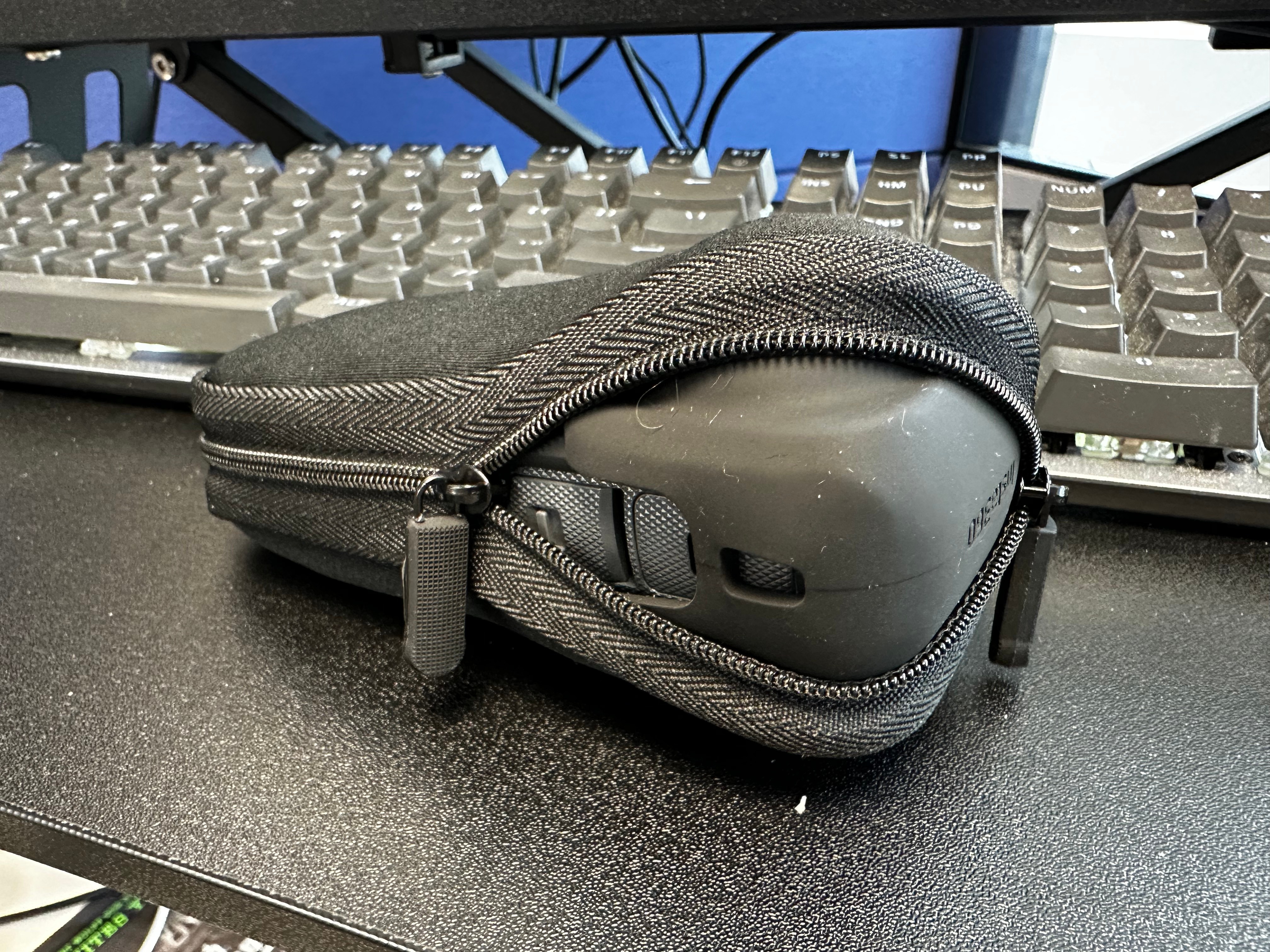
The included pouch cannot hold the X4 with the lens cap. It will hold the X4 with the included Thermo Cover Grip, though, and has pockets for the lens protectors and cleaning cloth. I would not put the USB-C cable in there, as it can stick out of the pocket and scratch your X4.
Firmware notes:
After activation, I see a random (?) WiFi password is assigned. An X3 firmware update gave us the ability to change the default 88888888 (which the X4 still defaults to, per videos I have watched). It looks like Insta360 now randomizes it so this step is not needed to prevent nearby folks from accessing and download all your files while your camera is on ;-) (I have not tested to see if the open access is still there, if you know the WiFi password, but I will soon.)
After activation, the firmware shows you about adding lens protectors, and changing settings to match what type you have (plastic, or premium). THere is also an “automatic” setting where it will try to detect that you are using lens protectors. I expect this means they impact stitching.
There is then a nice tutorial that walks you throgh the user interface – swiping up and down and such to navigate the menus.
THe user interface is fancier now. When a picture is taken, you see a small thumbnail appear, then fly off the screen. There are a few spiffy things like that I have noticed, so far.
You also get pop ups that warn you if lighting is too low for the mode you are in.
NEW from X3:
Lens Guard Mode – Auto, Standard, Premium, No Lens Gaurd
Screen Reader – “When on, the camera provides voice prompts for certain commands or actions.”
Prompt Sound – Now has “Adaptive” in addition to High, Medium, Low and Mute.
AI Highlights Assist – “AI will analyze video highlights during filming for faster editing on the Insta360 App.” It mentions this increased power consumption and temperature.
Gesture Control – this works well. Show a two finger “peace sign”, and you get a countdown (so you can move your hand) and it takes the photo. Hold you palm and it will start or stop recording. On this on/on screen is a little animation of a person showing how to do each one. (Scroll down to see the other. It was not intuitive that there was more below this animation; I expected it to just show me both.) THIS IS NEAT.
Timed Capture – The X4 has a clock. Turn this on, and you set a Start Time and Duration (which can be “infinite”) and a Repeat Frequency (Once, or Every day). You also set shooting mode (video, photo, all the modes, 360 or single lens, etc.) and parameters (resolution and frame rate), and image parameters (auto, ISO, etc.).
Audio Settings – adds “Auto Wind Noise Reduction.” Old “Window Noise Reduction” is now called “Active Wind Noise Reduction.”
There is a setting of all the quick access modes that now has defaults for Motorcycling, Skiing, and Outdoors. You can “+” to add a new one and pick from a list of presets (Surfing, Running, Biking, Cars, etc.). You can also Customize where you can make your own, and it will show as “Customize” or as one of the preset names you set it to. This is still not as good as being able to give it your own name, but better.
UPDATE: There is no USB setting. When you plug it in to a computer, you get a screen asking “U-Disk Mode” or “Reverse Charging”.
UPDATE: In addition to 5.7K, there is also 5.7K+. “”Close to 8K image quality but with a smaller file size. 5.7K+ is not suitable for low light conditions.”
UPDATE: While charging, the screen displays a circle and the percentage charged.
UPDATE: Automatic screen brightness! I missed the on screen button next to the slider. In a dark room, the screen goes dim. In bright light, the brightness increases so you can see it. Nice battery saver!
Settings has new options:
“Touch to activate when off”
“Power-off Charging” that tells what action happens when you plug in to charge (Charge only, Charge and power on, Charge and record). Charge and record could allow you hooking this up to a timed outlet and turning that outlet on to automatically start recording video, but I have not tested this yet.
Long press Shutter Button to cancel recording – nice. That saves a swipe, I guess.
Thermo Grip Cover – Automatic Recognitions, Installed or Uninstalled. A note about this – the cover has two white dots below it. I think that is how it knows the cover is installed. It also impacts stitching so you have to set the mode to match. The manual warns to not install or remove while recording or stitching will get messed up.
Date and Time – set by the app but you can set it here. I do not know how it deals with time zones. I suppose you’d just have to sync your phone to the camera when you get to the new time zone? You can change the Date Format as well (MM/DD/YY versus DD/MM/YY or YY/MM/DD).
Reset Tutorial – to go back and learn it all again.
There is alot here that wasn’t mentioned in any of the videos I watched, so I expect we will see Part 2 as the YouTubers get to play with the current firmware.
I will say again – this camera feels much larger and bulkier. I hope the added features are worth it.
More to come. Tonight I’ll try to record my X3-X4 comparison videos where I do some 5-10 minute clip without edits so folks can compare raw output rather than short demonstration clips.
UPDATE: Eat Sleep 360 posted a 3 minute video going over many of these options, and a few that I was unaware of.
2024-03-09 – Added Dropbox link for direct download, any more background details. I have let Roger know I am now ready to download the 1987 version files and get those available.
Last year, Roger Taylor went through the effort and expense to have the Tandy/Radio Shack Color Computer 3’s custom “GIME” chip decapped and scanned. Super high resolution images are available. This should give someone with the knowledge and skills the ability to reproduce these custom chips.
Read more about this, and other fascinating projects, on Roger’s Patreon page. Consider supporting him. He has made some interesting acquisitions lately, including a “did we know this existed?” Mexico CoCo 3 called a MicroSEP II. He has also spend thousands of dollars to acquire the source code archives of the late Steve Bjork.
Use this “1986 GIME.torrent” file to download with a BitTorrent client and help seed it for others to get a backup of these files. I also have the files in a Dropbox share for those really patient with downloading 140+ GB of image files.