I hate it when this happens… It looks like a 4TB drive in my 5-bay Drobo has gone out. Drobo cannot detect it. I have dual-drive redundancy enabled, so two drives can fail and I’d still have my data… Fortunately.
Drobo 5C showing a 4TB drive failure.
Hopefully, I won’t have two drives fail between now and the time my replacement drive arrives. :)
On the plus, drive prices have dropped since I bought these drives in 2019. I’ll begin the process of upgrading drives to 6TB models over coming months, money permitting.
If you had the original manual revision, you may have been taught things slightly different from later editions. For instance, clearing the screen. The CLS command can be followed by a number to fill the screen with a color.
But the early edition manual demonstrated this using parenthesis, which I’ve never seen done:
CLS(3)
It works. Try it :)
After a moment of thinking about this, I realized it’s just normal math grouping for numbers, like this:
PRINT 3*(5-1)
The parenthesis make sense there. But they sure look odd if you do this:
PRINT (42)
It works. Try it :)
And whoever wrote the manual was using them for CLS too. But why?
Not too long ago, I learned that the BASIC ROMs had other undocumented syntax. For instance, there is a Syntax for the PRINT command where you give a screen position using the @ symbol:
PRINT @96,"HELLO"
But the BASIC ROMs also look for (but do not require) the @ symbol after keywords LINE@, PAINT@, GET@ and PUT@. But I’ve never seen anyone code:
LINE@(0,0)-(255,191),PSET
It works. Try it :)
I expect there are other oddities in there, as well. One I recently discovered, just by trying it, had to do with device numbers.
Device numbers
I was surprised to find that the original Color BASIC manual did not cover all of the commands available. For example, printer listing with LLIST and PRINT#-2, or opening and reading/writing to/from cassettes. I expect later revisions may have added these, and maybe other, missing commands.
Folks using a printer learned that, while PRINT by itself goes to the screen, doing PRINT#-2 makes the output go to the printer.
#-2 is a device number. When accessing a cassette file, device #-1 is used:
OPEN "O",#-1,"TAPEFILE"
PRINT #-1,"THIS GOES TO THE CASSETTE FILE"
CLOSE #-1
Disk Extended Color BASIC added disk device numbers, and allowed opening up to ten files at a time using devices #1 to #10.
OPEN "O",#1,"DISKFILE.TXT"
PRINT #1,"THIS GOES TO A DISK FILE"
CLOSE #1
At some point, I became aware that device #0 was the screen. The use of it was optional, since PRINT by itself assumed screen.
PRINT "THIS GOES TO THE SCREEN"
PRINT #0,"SO DOES THIS"
It works. Try it :)
But, it was useful when creating a program that allowed the user to select output to screen or printer.
10 INPUT "OUTPUT TO S)CREEN OR P)RINTER";A$
20 IF A$="S" THEN DV=0
30 IF A$="P" THEN DV=-2
40 PRINT #DV,"THIS GOES TO SCREEN OR PRINTER"
I recall writing programs that would also allow outputting to a tape or disk file, so if one of those options was chosen, I would make sure to create the output file:
10 INPUT "OUTPUT TO S)CREEN, P)RINTER, T)APE OR D)ISK";A$
20 IF A$="S" THEN DV=0
30 IF A$="P" THEN DV=-2
40 IF A$="T" THEN DV=-1:OPEN "O",#-1,"TAPEFILE"
50 IF A$="D" THEN DV=1:OPEN "O",#1,"DISKFILE.TXT"
60 PRINT #DV,"THIS GOES TO... SOMEWHERE!"
70 IF DV=-1 THEN CLOSE #-1
80 IF DV=1 THEN CLOSE #1
Yuck. But you get the idea.
On a whim, I wondered what happened if you tried to CLOSE #0 (nothing). Or CLOSE #-2 (nothing). Then I wondered what happened if you tried to open those devices:
10 OPEN "O",#0,"SCREEN"
20 PRINT #0,"HELLO, SCREEN"
30 CLOSE #0
It appears BASIC just ignores OPEN/CLOSE to the screen device. And the printer:
10 OPEN "O",#-2,"PRINTER"
20 PRINT #-2,"HELLO, PRINTER"
30 CLOSE #-2
This means my multi-output program could have been made much, much simpler:
10 INPUT "OUTPUT TO S)CREEN, P)RINTER, T)APE OR D)ISK";A$
20 IF A$="S" THEN DV=0
30 IF A$="P" THEN DV=-2
40 IF A$="T" THEN DV=-1
50 IF A$="D" THEN DV=1
60 OPEN "O",#DV,"OUTFILE"
60 PRINT #DV,"THIS GOES TO... SOMEWHERE!"
70 CLOSE #DV
The only extra thing one might want to do is name the file different if going to disk (adding an extension), though you can do that to a tape file without error:
OPEN "O",#-1,"TAPE.TXT"
For tape, the filename can be up to 8 characters, with no extension. So the name would be “TAPE.TXT”. But if you had done “OUTPUT.TXT”, the tape name would be “OUTPUT.T” (8 characters). Not pretty, but it works.
Maybe we take care of that with:
10 INPUT "OUTPUT TO S)CREEN, P)RINTER, T)APE OR D)ISK";A$
20 IF A$="S" THEN DV=0
30 IF A$="P" THEN DV=-2
40 IF A$="T" THEN DV=-1
50 IF A$="D" THEN DV=1:EX$=".TXT"
60 OPEN "O",#DV,"OUTFILE"+EX$
60 PRINT #DV,"THIS GOES TO... SOMEWHERE!"
70 CLOSE #DV
That would add an extension (“.TXT”) only for disk files.
Anyway, I thought it was interesting that BASIC allowed OPEN/CLOSE on printer and screen devices, and I expect if I looked at the ROM disassembly, I’d find extra code there that just returns (not doing anything) when those device numbers are used.
Oh, and there is also a device #-3 in Extended Color BASIC, but you can’t do anything with it. That device number seems to be associated with the DLOAD command (which was removed on the CoCo 3) and is just used internally. But that’s the subject of a potential future article…
Radio Shack introduced the Color Computer in 1980. It came 4K or RAM, and Microsoft Color BASIC in the ROM. It could be expanded to 16K RAM, which allowed adding a second ROM for Extended BASIC. A plug-in disk interface cartridge came later, with it’s own ROM containing Disk BASIC.
I’ve often wondered what Microsoft used to write the CoCo BASIC ROMs in.
EDTASM+
Around 1982, Radio Shack released the EDTASM+ ROM-Pak for the Color Computer. It was a 6809 assembler for machine language, as well as a debugger. It could load and save files (source code and final binaries) to cassette tape.
There was also Disk EDTASM+, which added some extra features — though the most important one was probably that it could load and save to a disk drive, making that process far faster.
While the CoCo 1 and 2 were basically the same machine, just with redesigned circuit boards and enclosures, the 1986 CoCo 3 was quite different. It could operate in a double speed more, and provided up to 80 columns of text versus the original CoCo’s 32 columns. It also came with 128K — double what the CoCo 1/2 could handle — and could be expanded to 512K (though third party folks figured out how to do 1 an 2 megabyte upgrades).
Unfortunately, Radio Shack never released an update to the EDTASM+ ROM-Pak or disk software. It was still limited to the small memory and screen size of the original 1980 CoCo hardware.
Folks came up with various patches. I had one that patched my Disk EDTASM+ to run in 80 columns on the CoCo 3, in double speed more (faster assembling!) while setting the disk drive step rate to 6ms. It was a much nicer experience coding with long lines!
After this I moved on to OS-9, and used the Microware assemblers (asm and rma) from OS-9 Level 1 and Level 2. I am not sure I touched EDTASM+ again until I played with it on JS Mocha, decades later.
Hitatchi 6309
Hitcachi made a clone of the 6809. This replacement chip had some undocumented features such as more registers and more op codes. EDTASM+ couldn’t help with that, but there were some OS-9 compilers that were updated to support it.
That’s when folks like Robert Gault came to our rescue with enhancements for the original EDTASM+. Robert added support for the 6309, and many new features — including CoCo 3 compatibility.
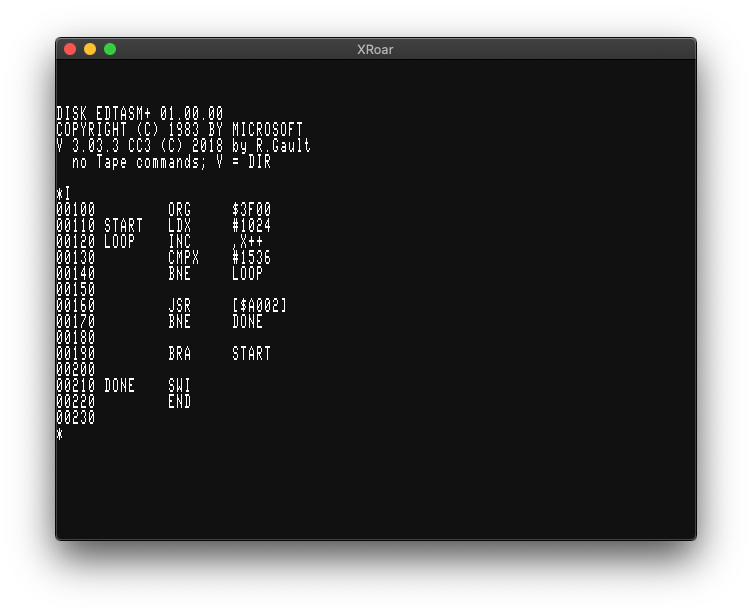
His EDTASM+ looks like this on a CoCo 3 in 80 column mode:
Robert Gault’s EDTASM+ update.
If you notice the copyright date, you’ll see he has continued to update and support it. Today he offers it in a variety of versions that run on the original CoCo 1/2, a CoCo 3, certain emulators, RGB-DOS support (for hard drive users), CoCoSDC (the modern SD card floppy replacement) as well as supporting things like DriveWire.
You can pick up your own copy for $35 as follows:
EDTASM6309 $35
Robert Gault
832 N.Renaud
Grosse Pointe Woods, MI 48236
USA
e-mail:	robert.gault@att.net
There are a number of new features added. Here is the list provided in the README.txt file:
CHANGES TO EDTASM (Tandy Version)
1) Tape is no longer supported; code has been removed.
2) Buffer size increased to over 42K bytes.
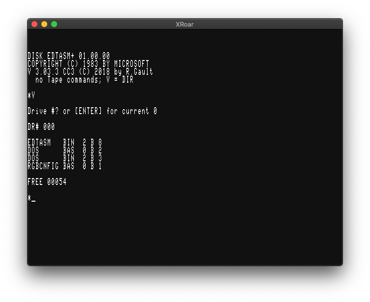
3) Directory obtainable from both Editor and ZBUG; V command.
4) Multiple FCB and FDB data per line.
5) FCS supported.
6) SET command now works properly.
7) Screen colors remain as set from Basic before starting EDTASM.
8) Symbol table printed in five names per line on Coco3.
9) On assembly with /NL option, actual errors are printed.
10) Warning error on long branch where short is possible.
11) ZBUG now defaults to numeric instead of symbolic mode.
12) RGB DOS users now have support for drive numbers higher than 3.
13) Hitachi 6309 opcodes are now supported for both assembly and disassembly
including latest discoveries.
14) HD6309 detection is included and if present incorporates a ZBUG error trap
for illegal opcodes and enables monitoring and changing the E,F,V registers
from ZBUG.
15) Coco 3 users can now safely exit to Basic and use their RESET button from
EDTASM.
16) Keyboard now has auto repeat keys when keys are held down.
17) Lower case is now supported for commands, opcodes, options, and symbols.
Take care when loading or saving files or using symbols, ex. NAME does not
equal name, \.A not= \.a, etc.
18) Local names are now supported. Format is A@-Z@ and a@-z@ for 52 local
symbols. New sets of locals are
started after each blank line in the source code. Local
symbols do not appear in or clutter symbol table.
19) Local symbols can only be accessed from ZBUG in expanded form:
ex. A@00023 not A@.
20) Now reads source code files that don't have line numbers. Writes normal
source files with line numbers ( W filename ) or without line numbers
( W# filename ).
21) Macro parameters now function correctly from INCLUDEd files.
22) While in the Editor, the U key will backup one screen in your source file.
23) DOS.BAS can be used to program the F1 and F2 keys on a Coco3. See below.
24) Coco3 WIDTH80 now uses 28 lines of text.
Coco 1&2 versions do require 64K RAM, the Coco 3 version will work with 128K
of RAM. You can assemble 6309 code even if your Coco has a 6809 cpu.
It also adds some new commands:
V - obtains a directory from either Editor or ZBUG modes.
U - scrolls backwards through source code.
FCS - is used exactly like FCC but automatically add $80 to the last character
in the string.
FCB, FDB - for multiple entries per line entries should be seperated by a
comma. Make sure that the comment field for that line DOES NOT CONTAIN ANY
COMMAS or an error will result.
New ‘V’ directory command in Robert Gault’s EDTASM+ update.
If you are wanting to do some CoCo assembly language programming, I highly recommend you sending $35 to Robert and pick up a copy of his version. EDTASM+ is tricky to learn, and his updates make it a bit less tricky.
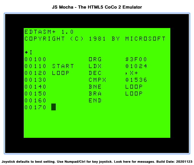
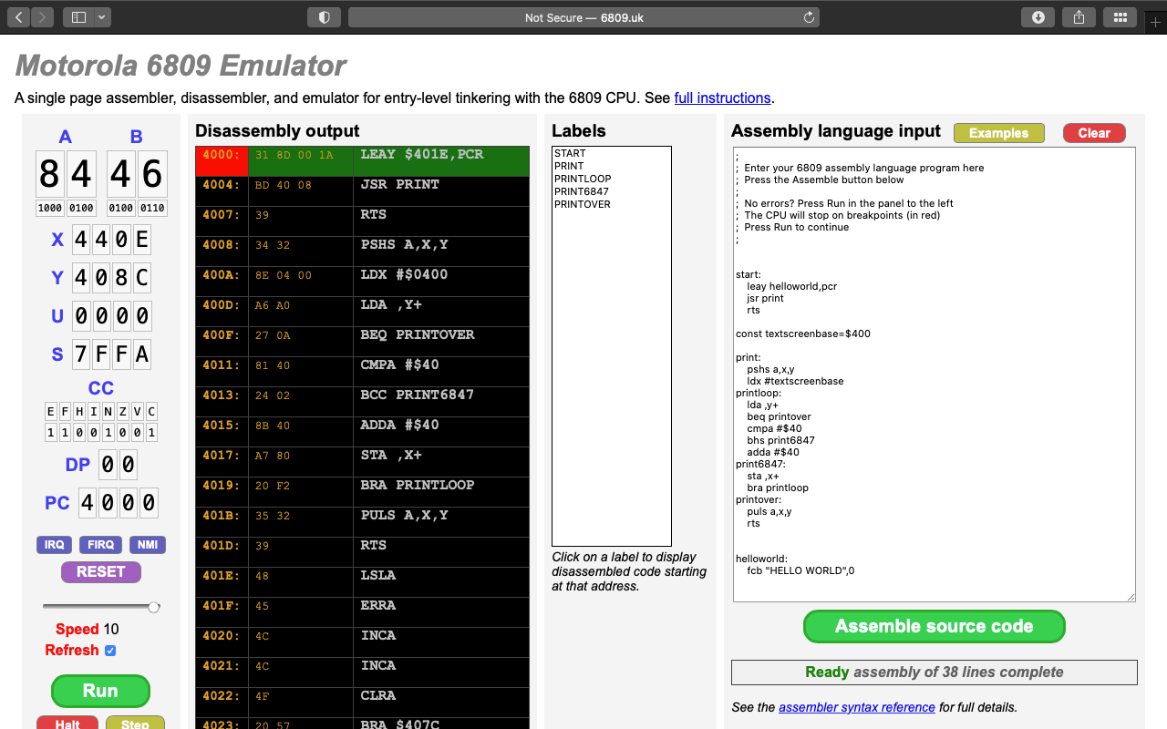
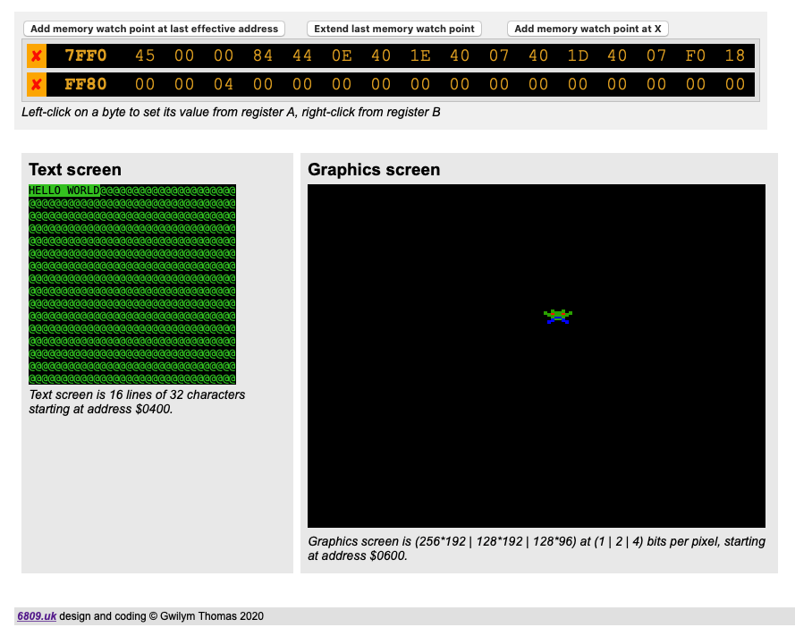
This website, “designed and coded” by Gwilym Thomas, is amazing. If has a spot where you can enter 6809 assembly source code, then you can compile and run it!
It even has a few sample programs you can select and try out.
While it runs, you see the registers update, as well as a source-level debugger showing what op codes are currently executing. You can set break points, and memory watch points, too.
It also provides text output in the form of the MC6847 VDG chip (used by the CoCo, and a few other systems). The graphics mode is different VDG. While it supports some similar resolutions, it also adds a 16-color display.
The screen memory is mapped to $400 (1024) just like the CoCo, so you can run stuff like this:
If you past that in to the Assembly language input window and then click Assemble source code, you will see the text characters in the Text screen preview window cycling through values. Neat!
The graphics screen starts just past the text screen at $600 (1536). I think that might be where it started on a non-Disk Extended Color BASIC system. (See my article about memory on the CoCo for more details.)
The documentation notes this about the modes:
The graphics screen is a memory-mapped display of 6144 bytes of RAM beginning at address $0600. There are 3 graphics colour modes, in which either 1, 2, or 4 bits represent a single pixel in 2, 4, or 16 colours respectively. Addresses increase left to right, top to bottom as for the text screen.
Columns and rows are zero-base with (0, 0) at the (left, top). Sequences of bits (1, 2, or 4) from high to low represent pixels from left to right. The 2 colour mode has 256 pixels by 192, the 4 colour 128 by 192, each line being 32 bytes. The 16 colour mode has 128 pixels by 96, each line being 64 bytes.
Example: in 4 colour (2 bit) mode pixel (93, 38) would be in byte $0600+(3832)+trunc (93/4), because there are 4 pixels in a byte. The colour value (0..3) would be stored in bits 5 & 4, ie. shifted left ((4-1)2)-((93 mod 4)*2 times).
Changing screen modes is NOT done via simulated VDG registers. Instead, it has code that looks like this:
    ldd #$0204       ; select 4 colour graphics mode
    swi3
I have not been able to find details on what values represent what mode. Also, the documentation says there is keyboard input:
Click the text screen panel then start typing for the emulator to receive keyboard input. Remember that (due to limitations of the emulated hardware) when lower case characters are printed to the screen they will appear in inverse video.
As far as the 6809 assembler goes, it does not parse all of the extensions that the LWTOOLS’ lwasm assembler supports, so I have been modifying my projects to be compatible with the emulator’s assembler. This has let me, with minor changes for things like ROM calls, test and debug my code in a way that is impossible on actual hardware.
2022-06-30 – Added details about adding Mercurial and retrieving source that way. Also added notes about building Toolshed (currently does not work) and NitrOS9.
A quick tutorial on how to get the Lost Wizard LWTOOLS running under Windows. I have tested this under Windows 11.
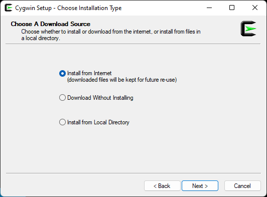
To build under Windows, you will need to use a compatibility layer that makes Linux-style code work under Windows. Lost Wizard recommends mingw or Cygwin. This tutorial will use Cygwin.
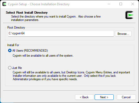
Click Next, then either use the default install location, or customize if you know what you are doing. Same thing for installing for “All Users” or “Just Me.” In my example, I am just using the defaults:
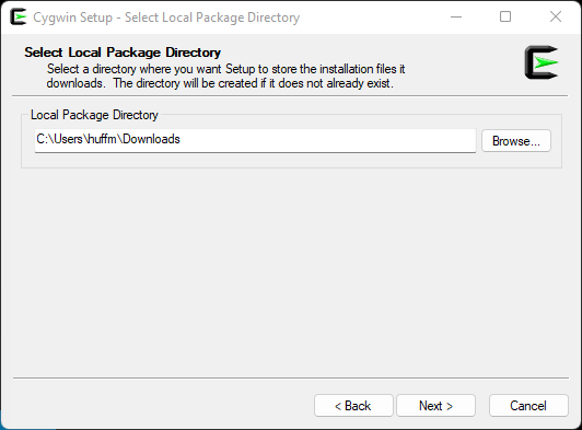
Click Next, then select where it will download files. I will just use the defaults:
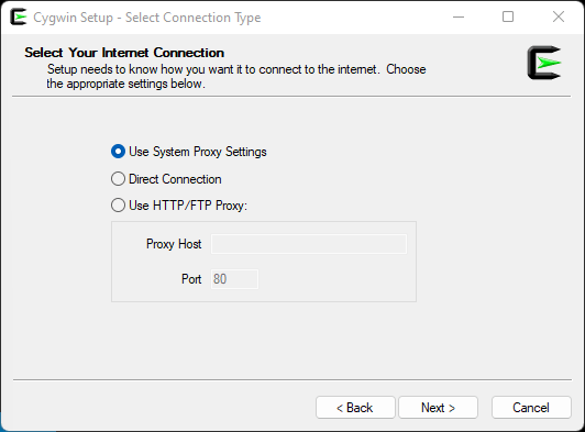
Click Next, and just use the default Internet Connection settings unless you know what you are doing and need to change them:
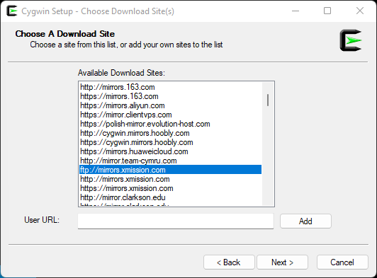
Click Next, then select one of the download sites. It shouldn’t matter which one you choose, but since I used to read the old Maddox website hosted on xmission.com, I selected that:
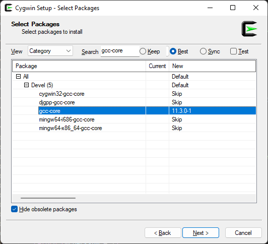
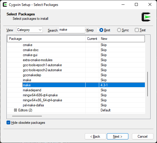
Click Next, and it will retrieve a list of available packages. For building LWTOOLS, you need a C compiler and “make” utility. I went with the standard GCC compiler and standard make.
Expand the “All” then “Devel” items.
Locate the entry that says “gcc-core” (or use the Search box) and click on the “Skip” to the right of it. It should change from “Skip” to a version number (currently 11.3.0-1 as I type this).
Locate the entry that says “make” and do the same (currently 4.3-1 as I type this).
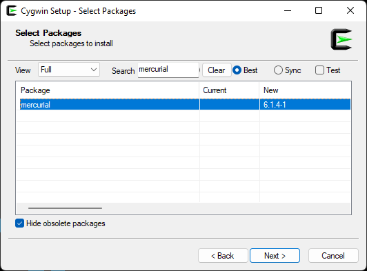
If you would like to download LWTOOLS (and other items) source directly rather than having to download “the most recent release”, you will also need to install “mercurial“. This will give you the “hg” command used to retrieve the latest source code for the projects. (And if you are doing all of this, might as well do this, too.)
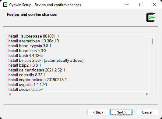
Click Next, and you will see a list of all the required packages that will be download. (When you select an item, this installer will download any other items that are required for the one you selected.)
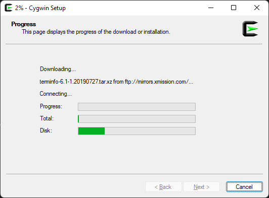
Click Next, and the download will begin.
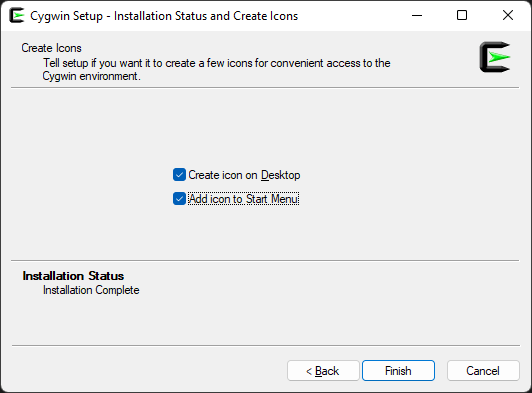
When completed, you can click Next and then choose if you want to add a Cygwin icon on your Desktop and/or in the Start Menu. Since you will need to run Cygwin to build LWTOOLS, you may want one or both.
Click Finish. You now have Cygwin!
Step 2: Download and extract the LWtools source code.
You can either download the source code and build that, OR you can use Mercurial to retrieve the latest version of the source (which currently includes a bug fix that is not in the release archive yet). Plus, it saves all the steps of extracting the gzipped tar file in 2b ;-)
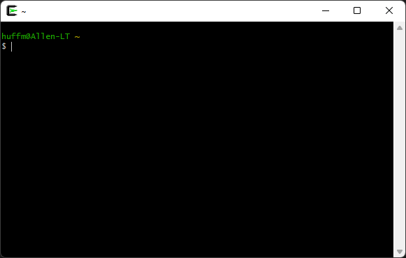
For either way, you will want to run “Cygwin64 Terminal” that is now installed. This will open up a console prompt.
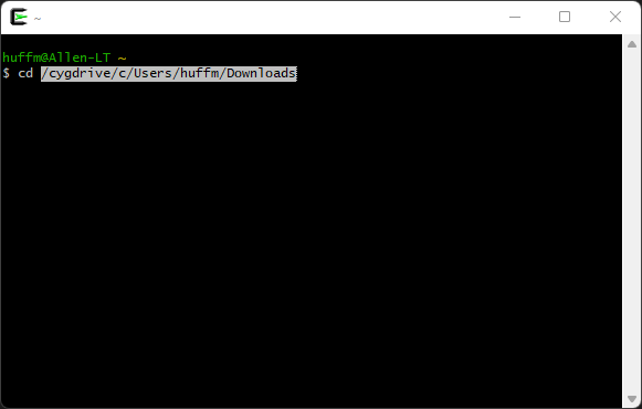
You will need to change directories to where you plan to download the LWTOOLS source code. Cygwin translates the Windows directories like “C:\Users\huffm\Downloads” to a Unix-style directory path like “/cygdrive/c/Users/huffm/Downloads” on my system. If you know how to change directories from a Windows Command Prompt, instead of going to “C:\whatever” you would change backslashes to forward slashes, and start with “/cygdrive/c/whatever”
Use the change directory (“cd”) command and change to where you downloaded the LWTOOLS .gz file.
An easy way to get this path is to type the change directory command in the Cygwin terminal window, followed by a space, (“cd “) and then drag the “Downloads” folder from a Windows Explore window IN to the Cygwin Terminal. It will type out the path to whatever folder you drag and drop there:
Press enter, and you should now be in the directory where you downloaded the LWTOOLS file. The Cygwin prompt will change to show you what directory you are in. Mine looks like this:
That will retrieve the latest source and place it in a subdirectory called “lwtools” from here you are. Once complete, proceed to Step 3.
2b. Download and extract the latest release.
OR, if you want to manually download the latest release…
Go to http://www.lwtools.ca/ and download the latest version (currently 4.19 as I type this). Save it to wherever you chose, above.
The download will be a gzipped .tar file, so you will need some tool to extract it. You can find something in the Windows Store, or just use a command line utility from Cygwin. For this tutorial, we will use the command line.
From this terminal, many Linux-style commands are available, including gzip (which we will use to extract the LWTOOLS .tar file) and tar (which we will use to un-tar that file).
Extract the .gzip file by typing “gzip -d” (for decompress) followed by the lwtools filename:
gzip -d lwtools-4.19.tar.gz
This should extract the “lwtools-4.19.tar” file in to that directory. Now un-tar that file by typing:
tar -xf lwtools-4.19.tar
That will finally leave you with a directory called “lwtools-4.19” (or whatever version you downloaded.
Step 3: Build and install LWTOOLS
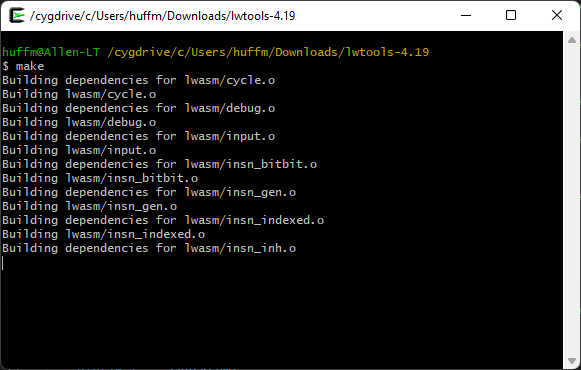
Change directories in to the “lwtools-4.19” directory (or, if you downloaded with Mercurial, in to “lwtools” or whatever you called it):
cd lwtools-4.19
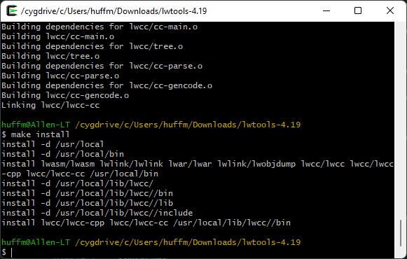
Once you are there, all you need to do is type “make” to begin the build process.
Once complete (it may take awhile), the binaries have been built, but they aren’t located where Cygwin can run them yet. To copy them over in to the proper location, type “make install“:
You now have some new command line programs available from within Cygwin. To verify that they worked, you can try typing them to see if they bring up their usage display. Try typing:
lwasm --usage
If you get back a “Usage:” message, you should now be ready to use LWTOOLS to compile 6809 assembly language for the CoCo.
4. Other things you may want to install
Toolshed is a series of commands for copying files from your PC in to disk image files used by emulators or things like the CoCoSDC.
NOTE: Currently, this will not work. Some rules have changed in the compiler and it will error out. There are about 12 places in the source that can easily be fixed to make it build, but I’m going to wait and see if the Toolshed maintainers have a solution.
hg clone http://hg.code.sf.net/p/toolshed/code toolshed
cd toolshed
make -C build/unix install
cd ..
NitrOS9 is a 6809 (or 6309) operating system based on Microware OS-9/6809.
hg clone http://hg.code.sf.net/p/nitros9/code nitros9
cd nitros9
make dsk
BONUS: Building a simple program.
As a simple test, use a text or code editor to create the following “helloworld.asm” file. You will need to know where you save this file, since you will be typing that on the command line to build it. On my system, I have all my .asm files in a directory, and I just “cd” to that directory from the Cygwin terminal.
This simple program will display the message “HELLO WORLD!”. It does this by using the Color BASIC “CHROUT” ROM call. This code starts by loading X with the address of a text message that is a series of characters, followed by a 13 (carriage return) and a 0 to mark the end of the message. The main loop loads the A register with whatever is at X, and if it is zero it ends. Otherwise, it calls the CHROUT routine indirectly by jumping to the location stored at $a002 in the ROM. It will repeat this until it gets to the 0 at the end of the message.
LWTOOLS can build .bin files that can be transferred to a CoCo (or emulator) on a disk image (using other tools), and then you can LOADM that file and EXEC it:
lwasm helloasm.asm -fdecb -ohelloasm.bin
Above, that takes the input file “helloasm.asm” and compiles it in format “decb” (a .bin binary) and calls the output file “helloasm.bin”. (You’d probably want all uppercase for filenames on the CoCo.) That should give a LOADM-able file to try.
But, a nifty feature of LWTOOLS is the ability to generate a BASIC program that loads the assembly language. Use the format “basic” and make the output file a “.bas” instead:
lwasm helloasm.asm -fbasic -ohelloasm.bas
That will create a text file called “helloasm.bas”:
10 READ A,B
20 IF A=-1 THEN 70
30 FOR C = A TO B
40 READ D:POKE C,D
50 NEXT C
60 GOTO 10
70 END
80 DATA 16128,16155,142,63,14,166,128,39,6,173,159,160,2,32,246,57,72,69,76,76,79,32,87,79,82,76,68,33,13,0,-1,-1
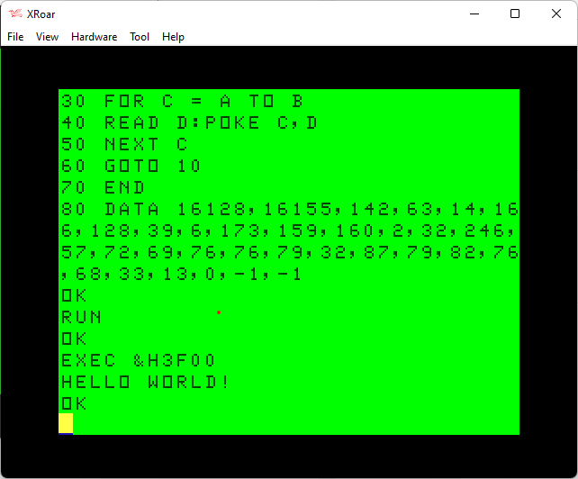
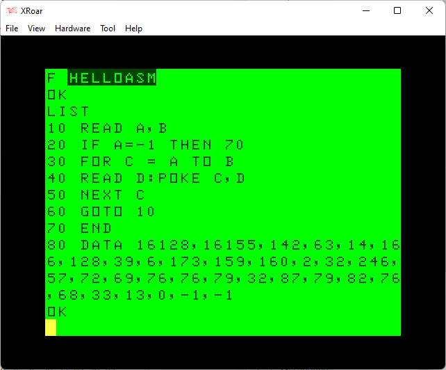
I like to use the XRoar emulator, since it lets me load a text file as if it was a cassette file. You can run XRoar, then use Ctrl-L (or File->Load) then select the “helloasm.bas” file. After that is done, typing “CLOAD” in XRoar will load this text file as if it was coming from tape!
Then you can “RUN” the program and load your assembly in to memory. For this example, the address of $3f00 was specified in the source codes “org” address (16128 in decimal) so that is where the code would load. After the “RUN”, you should be able to type “EXEC &H3f00” (or EXEC 16128 if not using Extended Color BASIC) and see the program run:
Okay, 6809 folks… In my 64K TRS-80 CoCo memory test article, I used an assembly language program of unknown origin to copy the CoCo’s ROM in to RAM. The “test” part is POKEing a byte in to ROM space and seeing if it now changes (since, on a 64K system, it would be running out of RAM).
The BASIC “OK” prompt is changed to read “OY” (after placing the 64K CoCo in to all-RAM mode).
That code looks like it was built for speed, moving 6 bytes at a time by using three 16-bit registers (X, Y and U). As a refresher, here is that code:
start:
    PSHS CC
    ORCC #$50
    LDY #$8000
loop1:
    STA $FFDE
    LDD ,Y
    LDX $02,Y
    LDU $04,Y
    STA $FFDF
    STD ,Y++
    STX ,Y++
    STU ,Y++
loop2:
    CMPY #$FEFC
    BCS loop1
    CMPY #$FF00
    BCC done
    STA $FFDE
    LDD ,Y
    STA $FFDF
    STD ,Y++
    BRA loop2
done:
    PULS CC
    RTS
I presented this routine as a BASIC loader program so one could easily type it in rather than needing an assembler and typing in assembly source code to compile.
For folks patient enough to type in a whole CoCo screen full of hexadecimal DATA statements, it works fine. But I thought it might be finer to present an even smaller program with less DATA statements.
The program size can almost be cut in half by eliminating the first loop that copies the 6 bytes at a time. Instead, I came up with something like this:
start:
    PSHS CC     Save CC
    ORCC #$50   Mask interrupts

    LDX #$8000  Start of ROM
loop:
    STA $FFDE   Enable ROM
    LDD ,X      Load D with whatever is at X
    STA $FFDF   Disable ROM
    STD ,X++    Store D at X and increment X
    CMPX #$FF00 Is X past end of ROM?
    BNE loop    If not, repeat

    PULS CC     Restore CC
    RTS         Return
The original “need for speed” version compiled to 53 bytes. This new version compiles to 25 bytes. That would make it much easier to type in, like this:
0 REM 64K ROM TO RAM (25)
10 FOR L=16128 TO 16152
20 READ V:POKE L,V
30 NEXT
40 EXEC 16128:POKE 44015,89
80 DATA 52,1,26,80,142,128,0
90 DATA 183,255,222,236,132
100 DATA 183,255,223,237,129
110 DATA 140,255,0,38,241,53
120 DATA 1,57
Is there anything I can do to save a few bytes in that ROM to RAM routine? Please share comments and suggestions.
Is there an easier way to detect 64K? (Hey, that rhymes!)
If the goal is to just test for the existence of 64K, all we really need to do is put the machine in RAM mode and try to modify a byte in the upper 32K. If it can be modified, 64K is there. Maybe there is an even smaller way just to do that?
In 64K, you have memory locations 0-65535 available ($0000-$FFFF). But, the last 255 bytes ($FF00-$FFFF) are used for I/O, and as far as I know, the RAM there cannot be accessed. (Is this correct?) That would mean the last byte of usable RAM on a 64K CoCo would be at $FF00-1 ($FEFF). If that is correct, all we need to do is switch to RAM mode, store a byte at $FEFF and then read it back and see if it is what we put there. If it is, 64K exists.
There is a ROM routine that will output whatever character is loaded in the A register. We could use that to print out a message if 64K exists. Since the goal is to make this as small as possible, the message could simply be ‘Y’. My first attempt was something like this:
start:
    PSHS CC     Save CC
    ORCC #$50   Mask interrupts.

    STA $FFDF   Disable ROM
    LDA #'Y     Load A with 'Y'
    STA $FEFF   Store A in last RAM byte
    CLRA        Clear A
    LDA $FEFF   Load A with last RAM byte
    CMPA #'Y    Compare to 'Y'
    BEQ done    If Y, done.
    LDA #'N     Else, load A with 'N'
done:
    STA $FFDE   Enable ROM
    PULS CC     Restore CC
    JSR [$A002] Output byte in A to console.

    RTS         Return
I disable the ROM (going in to “all RAM mode”), load A with a ‘Y’ character, then store it at $FEFF. I then clear A, then load A with whatever is at $FEFF. I compare A with ‘Y’ and if it is, I branch to the end where it will re-enable ROM, restore the CC register, then jump to the ROM routine that outputs whatever is in A. If it had no equaled ‘Y’, it would have not branched to ‘done’ and would instead load A with ‘N’, then complete, outputting ‘N’.
Running that should print out Y or N, depending on if 64K is detected.
And it works! But it is larger than the 64K ROM TO RAM code, taking up 32 bytes. I suppose there could be less typing since now the “ROM to RAM” program wouldn’t need to POKE the ‘OK’ prompt to show the user if it can be changed, so this probably is better.
0 REM 64KTEST1.BAS (32)
10 FOR L=16128 TO 16159
20 READ V:POKE L,V
30 NEXT
40 EXEC 16128
50 DATA 52,1,26,80,183,255,223
60 DATA 134,89,183,254,255,79
70 DATA 182,254,255,129,89,39
80 DATA 2,134,78,183,255,222
90 DATA 53,1,173,159,160,2,57
However … If we don’t want to be as user-friendly (printing a ‘Y’ or ‘N’), maybe some bytes could be saved by just setting a byte on the 32-column screen to indicate the result. I tried this:
start:
    PSHS CC     Save CC
    ORCC #$50   Mask interrupts.

    STA $FFDF   Disable ROM
    CLR $FEFF
    DEC $FEFF
    LDA $FEFF
done:
    STA $FFDE   Enable ROM
    PULS CC     Restore CC
    STA $0400

    RTS         Return
For this routine, I save CC and disable interrupts, then disable ROM. I then clear memory location $FEFF, and then try to Decrement whatever is there. If the CLR worked, it should be 0, and a DEC would turn it in to 255. To see what happened, I load A with whatever is at $FEFF, re-enable ROM, restore CC and then store whatever I loaded in to A to the top left of the 32 column screen. If 64K is present, an orange graphics block (255) should appear in the top left of the screen. If not, whatever value in ROM at $FEFF will be stored that. On my CoCo, that is a 0, so I should see an inverted ‘@’ sign appear on a non-64K system. This isn’t perfect, since if ROM just happened to contain 255 at that location, this test would not work.
This is 25 bytes of code. Still no savings, but the BASIC program could be smaller, which is the end goal:
0 REM 64KTEST2.BAS (25)
10 FOR L=16128 TO 16152
20 READ V:POKE L,V
30 NEXT
40 EXEC 16128
50 DATA 52,1,26,80,183,255,223
60 DATA 127,254,255,122,254
70 DATA 255,182,254,255,183
80 DATA 255,222,53,1,183,4,0,57
Line 40 should really be “CLS:PRINT:EXEC 16128”, otherwise the user would have to make sure they weren’t at the end of the screen when they ran it, since the next output would scroll and overwrite whatever the program POKEd to the top left of the screen.
The discussion continued in a follow-up article I posted a bit later. Check out those two postings, as well as the comments, for the full discussion. In the end, I used a suggested approach of encoding the length of each line (the number of characters to print as a centered string) in ASCII, so an ‘A’ represented one, ‘B’ would be two, and so on. To convert ASCII to the values needed, the program would do a subtract 64:
On May 30, Sebastian T posted a new comment to that article with a suggestion that would reduce this program’s 64-byte size to 61 by getting rid of the “-64” bytes:
It would be nice to get rid of the “-64” part after the ASC() function, as this would save another 3 bytes, reducing the program size from 64 to 61 bytes.
All you have to do is to replace the characters inside the string with lower ASCII values just as needed, like &H01, &H03, &H05 and so on.
– Sebastian T. (5/30/2022)
Indeed, if instead of having “A”, “B”, “C”, etc. you could put in the raw bytes of 0, 1 and 2, that subtraction would not be needed. It is possible to alter BASIC programs to do this, but they create programs that are impossible for a user to type in from a listing. (I experimented with such a trick when I was working on a BASIC Pac-Man program.)
Or so I thought. Sebastian continued with a very clever approach/solution to typing in an un-typeable program:
You cannot use the keyboard to edit the string in this way, but I did write some self-modifying code that replaced the characters directly in program memory. After this, you can erase the extra code and you are left with a fully functional version that is 61 bytes long.
– Sebastian T. (5/30/2022)
What an interesting approach! Provide a fully typeable BASIC program which contains self-modifying code. Run the routine that self-modifies, then delete the self-modifying routine and save out the final program. Here is Sabastian’s example:
0 FORC=1TO14:W=ASC(MID$(“ACEGCGKOEKQWCC”,C)):PRINTTAB(16-W/2)STRING$(W,42):NEXT
10 ‘
20 ‘FIND FIRST STRING IN THE BASIC PROGRAM MEMORY AND HACK IT!
30 S=PEEK(25)256+PEEK(26) ‘START OF BASIC CODE IN MEMORY
40 E=PEEK(27)256+PEEK(28) ‘END OF BASIC CODE IN MEMORY
50 FOR A=S TO E
60 IF F THEN READ V : IF V<0 THEN END ELSE POKE A,V
70 IF PEEK(A)=34 THEN F=-1 ‘TOGGLE FLAG UPON REACHING THE FIRST QUOTATION MARK
80 NEXT A
90 DATA 1,3,5,7,3,7,11,15,5,11,17,23,3,3,-1
Sebastian concludes:
Run it once, then do a DEL 10-90. Run it again to verify it still fulfills the original task, and it does!
Some comments:
1) All tests done in XROAR 1.0.1 emulating a COCO 1 with 32k RAM.
2) I removed the “-64” before modifying the string, but you can also do it afterwards, even though the EDIT function will behave a bit funny while skipping over the non-printable characters in the string constant, but it works. I tested both ways.
3) If one of the characters had been 0 or 34 (quotation mark) this would have not worked. But this was not the case, so I got away with this. I’m not sure if there are other forbidden characters to consider, if somebody knows about this please comment.
4) In order to make sure this was still a valid program, I CSAVE’d it in a virtual cassette file, did a cold restart and reloaded the saved program. It works!
5) If you LIST the program, you’ll see a supposedly empty string inside the MID$() function, however it is not empty! I wrote a small memory monitor to verify this.
6) RENUM function won’t work now, though.
In summary, this trickery allows reduction of the final program size from 64 to 61 bytes.
Best regards!
– Sebastian T. (5/30/2022)
What an interesting approach. One can now type in a longer BASIC program, run it, DELete some lines, then end up with a smaller final program.
For BASIC programmers who used modified code for things like this, I suppose they were doing something like this. There would be a master program that could be edited and worked on, with routines at the end to modify strings and such, and then after the modification was ran, a second copy would be saved that could not be easily edited later.
And now we have a two-step way of creating a 61 byte version of that program.
I recently had a request on Fiverr to try to shaper up an out-of-focus video. I thought I might be able to do it using Topaz Labs Video Enhance AI. After several attempts, I concluded that this was not the right tool for the job. While it did have the ability to sharpen video, even on the highest settings it was not sufficient.
Instead, Ida at Topaz Labs support suggested converting the video in to individual images and processing them through their Topaz Labs Sharpen AI product. After a number of attempts to convert the video to individual images, I ended up using the open source FFmpeg program.
Convert movie to images
Using the option “-i” to specify the input video file, and “-vf” for the video filter with the options “fps” for how many frames per second to process and finally the output filename format.
For fps, if you want to capture every frame of the video, set this to the frames per second of the video file. In this example, the original video was 25 frames per section:
ffmpeg.exe -i VIDEO.MP4 -vf fps=25 out%d.png
For the output filename, you can use C printf-style variables such as %d so it knows where to place the number in the filename. Above, that would produce “out1.png”, “out2.png”, and so on.
Once you have all the frame images, they can be imported in to Sharpen AI and processed. This will produce new output filenames adding “-SharpenAI-Focus” or similar to the filename. You can then reassemble those individual images back in to a movie.
Convert images to movie
The option “-framerate” is used to generate that many frames per second in the new movie file. It should match the -fps value used above.
“-i” is used to tell FFmpeg what filenames to look for. It will also use the C printf-style parameters. Since Sharpen AI takes “out1.png” and creates a new file called “out1-SharpenAI-Focus.png” (when using the focus mode), I needed to match that filename.
The first video I created would not play, and I found setting “-pix_fmt” would make a playable MP4 file.