See Also: part 1 and part 2 (coming soon).
This is a followup to a recent post I made about making a string in Color BASIC contain data from the text screen memory.
ASCII me no questions…
Color BASIC deals with a version of ASCII where specific numbers represent specific characters/letters:
https://en.wikipedia.org/wiki/ASCII
On the old school 8-bit home computers, not all of them used ASCII. Commodore used a variation called PETSCII, and the Atari 8-bits used ATASCII. While the trick discussed in this article might work on other systems that have a VARPTR or similar command, this discussion will be specifically about the character set in the Radio Shack Color Computer.
ASCII 65 is the uppercase letter ‘A’
PRINT CHR$(65)
A
If you POKE the value of 65 to the first position on the 32×16 text screen (location 1024), you will also see an uppercase 65.
POKE 1024,65
However, the embedded font data in the MC6847 VDG video generator chip does not follow ASCII for all of its characters. For example, CHR$(0) to CHR(31) are non printable characters. On the CoCo, two of them do something special — CHR$(8) will print a backspace and CHR$(13) will print an ENTER:
PRINT "HELLO";CHR$(8);"THERE";CHR$(13);"HOWDY"
HELLTHERE
HOWDY
It would have been nice if the CoCo could have done a beep for CHR$(7) like Apple 2s did, or clear the screen with CHR$(12) like many other systems did, but those are the only two that do anything other than “print nothing” on the CoCo.
If you POKE around a bit…
While you will not see anything if you PRINT those characters, if you POKE those values to the screen memory you will see something. For example, you could POKE characters 0 to 31 to the first row of the 32 column text screen like this:
FOR A=0 TO 31:POKE 1024+A,A:NEXT
The character set in the video chip has 0-31 representing reverse video characters “@” (AT sign) to “<-” (left arrow). We can expand that loop to POKE the first 128 characters onto the video screen:
FOR A=0 TO 127:POKE 1024+A,A:NEXT

But for PRINTing the ASCII characters, we have already established nothing shows up for characters 0-31, but things do PRINT when for 32-128:
FOR A=32 TO 127:PRINT CHR$(A);:NEXT

I put together this sloppy program that will show the differences, 32 characters at a time, of what you get when you PRINT the character values versus POKE the character values:
0 'POKEPRNT.BAS
10 CLS

20 PRINT@0,"PRINT 0-31:"
30 FOR A=0 TO 31:PRINT CHR$(A);:NEXT
40 PRINT@64,"POKE 0-31:"
50 FOR A=0 TO 31:POKE 1120+A,A:NEXT

60 PRINT@128,"PRINT 32-63:"
70 FOR A=32 TO 63:PRINT CHR$(A);:NEXT
80 PRINT@192,"POKE 32-63:"
90 FOR A=0 TO 31:POKE 1248+A,32+A:NEXT

100 PRINT@256,"PRINT 64-95:"
110 FOR A=64 TO 95:PRINT CHR$(A);:NEXT
120 PRINT@320,"POKE 64-95:"
130 FOR A=0 TO 31:POKE 1376+A,64+A:NEXT

140 PRINT@384,"PRINT 96-127:"
150 FOR A=96 TO 127:PRINT CHR$(A);:NEXT
160 PRINT@448,"POKE 96-127:"
170 FOR A=0 TO 31:POKE 1504+A,96+A:NEXT

999 GOTO 999
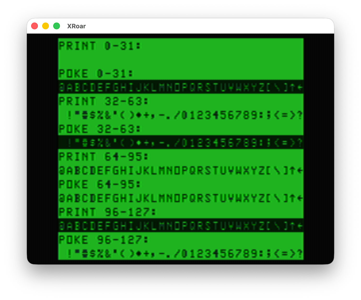
Looking at this, you can see only the characters 64-95 match between PRINT and POKE.
This means that the “copy screen to a string” concept from my earlier post doesn’t really do what we might expect. It does copy the data, but if we PRINT it back, we do not get back exactly what we started with.
This is the same thing that would happen if you tried to build a string by using PEEK from screen memory. This example prints stuff on the first line of the screen, then builds a string made of up characters using the PEEK value of that first line:
0 'PEEK2STR.BAS
10 CLS
20 PRINT "HELLO, WORLD! THIS IS A TEST."
30 FOR A=1024 TO 1024+31
40 A$=A$+CHR$(PEEK(A))
50 NEXT
60 PRINT "PEEKED STRING:"
70 PRINT A$
And running that shows this awfulness…
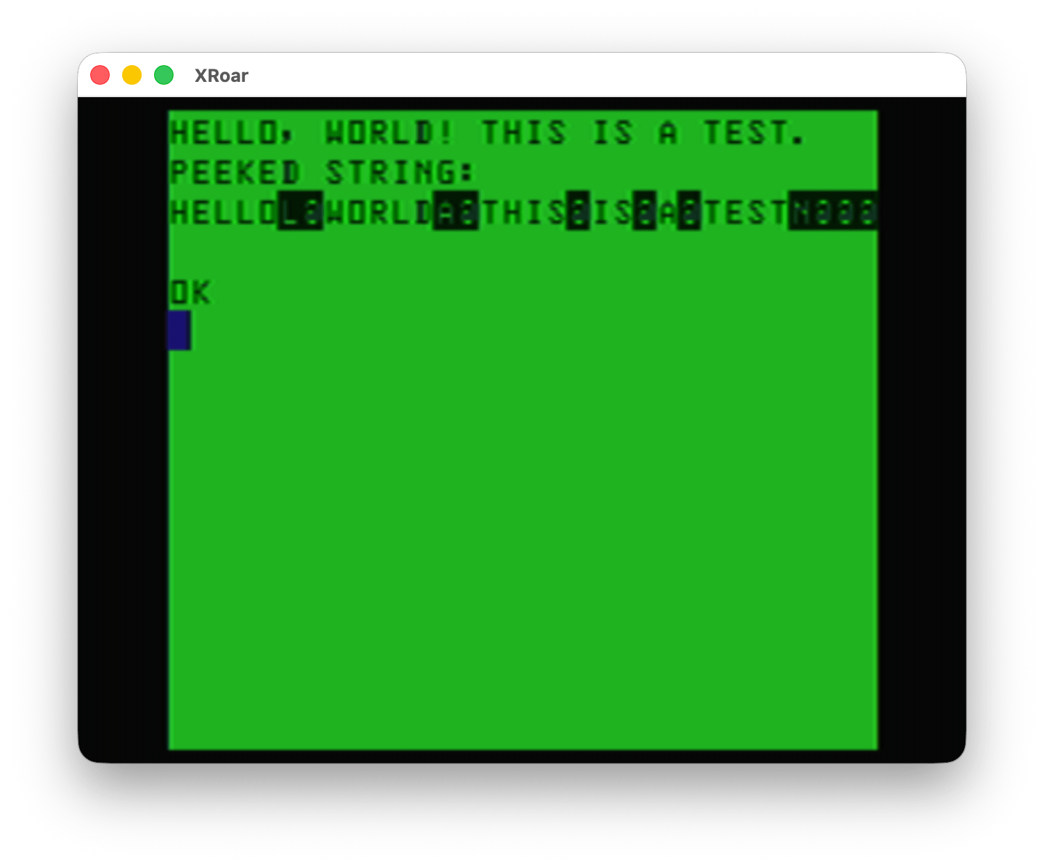
Yuck!
But that’s okay since there is not much use to copying TEXT data and then putting it back with PRINT. PRINT is fast, and we can easily PRINT that text data. Sure, there could be benefits if stuff being PRINTed is doing calculations and such to generate the output, but this trick won’t help there.
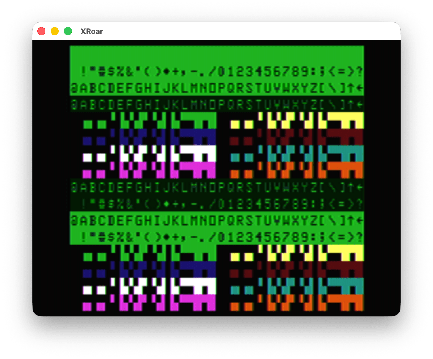
However, the semi graphics characters (128-256) are the same between PRINT and POKE.
0 'POKEPRT2.BAS
10 CLS
20 FOR A=0 TO 255
30 PRINT@A,CHR$(A);
40 POKE 1280+A,A
50 NEXT
60 GOTO 60
The top half is the PRINT CHR$ and the bottom half is the POKE:
Since there is no way on the CoCo to type those semi graphics characters into a string (pity, the later MC-10 could do this), we are forced to PRINT them like this:
PRINT CHR$(128);CHR$(128);CHR$(128)
That would print three black blocks. To speed things up, we could pre-generate a string of those three black blocks then we can PRINT that string very fast later:
A$=CHR$(128);CHR$(128);CHR$(128)
PRINT A$
And now you know why I chose to do a “splash screen” example for my demo in part 1. I initially tried it using the TEXT characters and quickly remembered why that can’t work (as explained here).
But it’s still a neat trick.
Bonus: This is stupid
For dumb fun, here is a program that makes A$ be whatever is on the first 32 character line of the screen.
0 'DUMBSTRN.BAS
10 A$="":A=VARPTR(A$):POKEA,32:POKEA+2,4:POKEA+3,0
When you RUN that, doing a PRINT A$ will show a 32 character line that is whatever was on the first line of the screen. If you do a “CLS” to clear the screen and show “OK” on the top line, then PRINT A$, you will see “OK” followed by 30 reverse @ symbols, which is CHR$(96) — but in video memory, a 96 is an empty block (space).
And with that, I’m going to stop now.
Unit next time…