Author Archives: Allen Huffman

About Allen Huffman

Co-founder of Sub-Etha Software.

Exploring Atari VCS/2600 Adventure – part 2

See also: part 1, part 2, part 3, part 4 … and more to come…

How the rooms are defined

In the previous installment, I introduced how the playfields were encoded in the Atari Adventure game. I had converted the assembly data into C code and made a command-line program that would print out the room graphics.

Atari Adventure screen graphics decoded in C.

I then recreated the process in Microsoft Color BASIC on a Radio Shack Color Computer emulator.

My command-line C program was displaying on an 80-column Windows command prompt window (or Mac OS X terminal) so it had plenty of room to render the 40 pixel wide playfields. The CoCo’s 32-column screen could not, so I changed the BASIC version to use low-resolution (64×32) text-mode graphics. This also let me use colors, though the CoCo only had 8 foreground colors to work with in this mode, with some restrictions from the Motorola MC6847 video display chip.

Atari Adventure screen graphics plotted in Color BASIC.

The end result was a proof-of-concept showing I was decoding the cartridge data properly, even if I couldn’t render it exactly as the Atari VCS/2600 would have.

There is much more I need to explore. For instance, each room has a definition data structure that describes things like which graphics data to use, how it is displayed (right half of the screen reversed vs mirrored, thin line on the left or white wall), its color, as well as which rooms are connected to it (Up, Left, Down and Right). Here is an example of the yellow castle data structure bytes:

LFEB4: .byte <CastleDef,>CastleDef,$1A,$0A,$21,$06,$03,$02,$01

The first entry (CastleDef) is a two byte pointer to the graphics data elsewhere in the ROM:

;Castle Definition                                                                                                 
CastleDef:
  .byte $F0,$FE,$15 ;XXXXXXXXXXX X X X      R R R RRRRRRRRRRR                                      
  .byte $30,$03,$1F ;XX        XXXXXXX      RRRRRRR        RR                                      
  .byte $30,$03,$FF ;XX        XXXXXXXXXXRRRRRRRRRR        RR                                      
  .byte $30,$00,$FF ;XX          XXXXXXXXRRRRRRRR          RR                                      
  .byte $30,$00,$3F ;XX          XXXXXX    RRRRRR          RR                                      
  .byte $30,$00,$00 ;XX                                    RR                                      
  .byte $F0,$FF,$0F ;XXXXXXXXXXXXXX            RRRRRRRRRRRRRR   

Note that the comments above are misleading. The graphics data only describes the left side of the images (the “X” characters in the comment). The right is created as the room is displayed, based on a bit in the fourth byte of the data. Here are what all the bytes mean:

;Room Data
;Offset 0 : Low byte room graphics data.
;Offset 1 : High byte room graphics data
;Offset 2 : Color
;Offset 3 : B&W Color
;Offset 4 : Bits 5-0 : Playfield Control
;            Bit 6 : True if right thin wall wanted.
;            Bit 7 : True if left thin wall wanted.
;Offset 5 : Room Above
;Offset 6 : Room Left
;Offset 7 : Room Down
;Offset 8 : Room Right

Looking at that data again, we can describe is as:

  • CastleDef – 2 byte pointer to graphics data.
  • $1A – Color.
  • $0A – B&W Color (the color to use with the Atari color switch is set to Black and White).
  • $21 – Attributes for how to display the room.
  • $06 – Room above (up).
  • $03 – Room left.
  • $02 – Room down.
  • $01 – Room right.

This early disassembly did not specifically describe what offset 4’s bits 5-0 mean, but one of them makes the room mirror (both sides look the same) versus the default of reversed. (Odd description. To me, a mirror reverses an image. It’s more like Duplicate versus Mirror in my mind. But I digress…)

The castle is a standard Reversed room:

XXXXXXXXXXX X X X      R R R RRRRRRRRRRR                                      
XX        XXXXXXX      RRRRRRR        RR                                      
XX        XXXXXXXXXXRRRRRRRRRR        RR                                      
XX          XXXXXXXXRRRRRRRR          RR                                      
XX          XXXXXX    RRRRRR          RR                                      
XX                                    RR                                      
XXXXXXXXXXXXXX            RRRRRRRRRRRRRR  

It’s attributes of $21 are the bit pattern 00100001.

One of the black castle mazes is Mirrored. Here is the room that contains the secret “dot” which is used to access the hidden easter egg room:

;Black Maze #3
BlackMaze3:
  .byte $F0,$F0,$FF ;XXXXXXXX    XXXXXXXXMMMMMMMM    MMMMMMMM
  .byte $30,$00,$00 ;XX                  MM
  .byte $30,$3F,$FF ;XX    XXXXXXXXXXXXXXMM    MMMMMMMMMMMMMM
  .byte $00,$30,$00 ;      XX                  MM
  .byte $F0,$F0,$FF ;XXXXXXXX    XXXXXXXXMMMMMMMM    MMMMMMMM
  .byte $30,$00,$03 ;XX          XX      MM          MM
  .byte $F0,$F0,$FF ;XXXXXXXX    XXXXXXXXMMMMMMMM    MMMMMMMM

Note how that “box” is made up by the Mirroring of the left half. Neat! That room is defined as:

LFED8: .byte <BlackMaze3,>BlackMaze3,$08,$08,$24,$13,$16,$13,$14

Its attribute of $24 is the bit pattern of 00101000.

And in the game, the room below and to the right of the castle has a thin right wall:

Atari Adventure room with a thin right wall.

If I understand which room this it, this is the data that draws it:

;Left of Name Room 
LeftOfName:
  .byte $F0,$FF,$FF ;XXXXXXXXXXXXXXXXXXXXRRRRRRRRRRRRRRRRRRRRRRRR                                  
  .byte $00,$00,$00
  .byte $00,$00,$00
  .byte $00,$00,$00
  .byte $00,$00,$00
  .byte $00,$00,$00

;Below Yellow Castle
BelowYellowCastle:
  .byte $F0,$FF,$0F ;XXXXXXXXXXXXXXXX        RRRRRRRRRRRRRRRRRRRR   **Line Shared With Above Room ----^ 

Note a clever technique programmer Warren Robinett used to save three bytes of ROM space. The room definition points to the “LeftOfName” data and a room is 21 bytes. The bottom of that room (a wall with an opening in the middle) is the same as the top of another room, so the definition uses three bytes for the next room data for the last three bytes of the first room. Clever!

The definition of the “Left Of Name” room (because the hidden easter egg room with Mr. Robinett’s name is to the right of this room) is:

LFE36: .byte <LeftOfName,>LeftOfName,$E8,$0A,$61,$06,$01,$86,$02

Its attribute of $61 is the bit pattern 01100001.

And down and to the left of the castle is a room with a thin left wall:

Atari Adventure room with a thin left wall.

Grrr. That Yorgel the yellow dragon ate me while I was trying to take this screen shot.

If I am reading things correctly, I believe this uses the same graphics data as the room below the yellow castle (opening at top, wall at bottom, no walls on left or right):

LFE24: .byte <BelowYellowCastle,>BelowYellowCastle,$D8,$0A,$A1,$08,$02,$80,$03

And its attributes of $A1 is the bit pattern 11000001.

So we have:

  • 00100001 – Reversed (castle).
  • 00101000 – Mirrored (maze).
  • 01100001 – Reversed and thin right wall.
  • 10100001 – Reversed and thin left wall.

Thus, looking back at the bit definitions:

;Offset 4 : Bits 5-0 : Playfield Control
;            Bit 6 : True if right thin wall wanted.
;            Bit 7 : True if left thin wall wanted.

It looks like we have:

  • Bit 0 – Right half of screen is Reversed.
  • Bit 1 – ?
  • Bit 2 – ?
  • Bit 3 – Right half of screen Mirrored.
  • Bit 4 – ?
  • Bit 5 – ?
  • Bit 6 – Thin right wall.
  • Bit 7 – Thin left wall.

It will take some more code exploring to see what bits 1, 2, 4 and 4 are used for, but understanding what controls Reverse and Mirrored was needed to properly draw the screens. One of those bits is probably used for rendering the “invisible” mazes, but I haven’t gotten to those yet.

Query: What happens if both bit 0 (Reverse) and bit 3 (Mirrored) are on? Why would those be separate bits? Perhaps there was an efficiency reason for checking for a set bit (less instructions than checking for a clear bit?) or perhaps bit 3 is something else. I guess I need to do more checking in to this, too.

The last bit of data (I’m assuming you can figure out “Color” and “B&W Color” entries) is the bytes that show which room is up, left, down or right. This is used by the game engine so it knows which room to display when the player moves off the current screen.

I’ll discuss that in a future installment. It’s not as straightforward as it seems. Here’s a quick teaser:

The “LeftOfName” room (solid walls with an opening at the bottom) is defined as:

LFE36: .byte <LeftOfName,>LeftOfName,$E8,$0A,$61,$06,$01,$86,$02

The room exists are defined as up ($06), left ($01), down ($86) and right ($02). But there are only 30 rooms ($00 to $1e) so there can be no room $86 (134). Maybe it actually means $06 with the high bit set (100000110). But room $06 is commented as “Bottom of Blue Maze” and looks like this:

BlueMazeBottom:
XXXXXXXX  XX  XX        RR  RR  RRRRRRRR
XX    XX      XX        RR      RR    RR
XXXX  XXXXXXXXXX        RRRRRRRRRR  RRRR
XXXX                                RRRR
XXXXXXXX                        RRRRRRRR
      XX                        RR                                            
XXXXXXXXXXXXXXXXXXXXRRRRRRRRRRRRRRRRRRRR 

…and that most definitely isn’t the room below the “Left of Name” room.

And, this room is different between game 1 (“Small Kingdom”) and games 2 and 3. In game 1, it’s a room with an opening at the top, and in games 2 and 3 it is part of an invisible maze.

This will have to be figured out.

Until then…

Benchmarking the CoCo keyboard – part 4

See also: part 1, part 2, part 3, part 4, part 5, part 6, part 7 and more (coming “soon”).

NOTE: I have a really great comment to share with you from a recent installment, but it deserves an article of it’s very own. Thank you, Jim, for the assembly sample. I’ll be getting to that soon…

Meanwhile, William Astle once again comments with some explanations to move this topic forward:

The KEYBUF thing is actually a lot more straight forward than it looks. It basically holds the result of reading FF00 for each keyboard column as of the last time KEYIN ran. More specifically, the last time it got to actually reading that column since it stops as soon as it finds a new key press and, so, it won’t necessarily update all eight entries in KEYBUF every time. It will when no new keys are pressed, though.

Basically, what it does is this:

Read the data from FF00
EOR it with the relevant byte in KEYBUF; this sets any bit where the value has changed since the last read; that is, a key was pressed or released. Exclusive OR yields a 1 if its two inputs are different and a 0 if the two inputs are the same.
AND the result of (2) with the KEYBUF value. This will keep only bits where the previous result was a “1” (not pressed). That ignores any keys that were released or are held down (previous state being a “0” in both of those cases).
Store the value read from FF00 into the KEYBUF byte using a copy of the original read from FF00.
If The result of (3) is nonzero, it stops reading the PIA and decodes the new keypress, does the debounce thing, etc.

KEYIN also masks off the joystick comparator input so you won’t see that in KEYBUF. Further, when reading the column with SHIFT in it, it masks that as well. So you can’t test for shift by looking in KEYBUF.

Basically, what the POKEs do is trick KEYIN into thinking that no keys in those particular columns were previously pressed by setting the bits to “1”.

As a side note, you can detect keys that are currently pressed by PEEKing KEYBUF. As long as Basic is doing its BREAK check, KEYIN is getting called at least once before every statement so KEYBUF gets updated.

William Astle

I’m glad there’s someone around here who understands this stuff. But it was his last paragraph that caught my attention. If we can just PEEK those values, INKEY$ isn’t even necessary (offering a slight speedup, perhaps).

Let’s look at what’s inside those eight KEYBUF locations. To make them fit on a 32 column screen, I will print them out as HEX values:

0 REM keyboard.bas
10 FOR A=338 TO 345:POKE A,&HFF
20 PRINT HEX$(PEEK(A))" ";
30 NEXT:PRINT:GOTO 10

Run this and you will see eight columns of hex values that represent the KEYBUF status of most of the keys. And by POKEing each value to 255 (&HFF for speed) before they are read, it allows detecting the key as long as it is being held down. You can now see the status of the arrow keys, including if you pressed two at the same time (Up+Left).

Let’s display this in bits so we can visualize which bits we care about:

0 REM keyboard2.bas
5 POKE 65495,0:CLS:FOR BT=0 TO 7:BT(BT)=INT(2^BT):NEXT
10 PRINT@0,;:FOR A=338 TO 345:POKE A,&HFF:PRINT A;:V=PEEK(A)
20 FOR BT=7 TO 0 STEP-1:IF V AND BT(BT) THEN PRINT "1"; ELSE PRINT "0";
30 NEXT:PRINT:NEXT:GOTO 10

Running this will display eight lines representing the bits in each of those memory locations. Here is what it looks like when all four arrow keys are held down at the same time:

CoCo Keyboard Matrix with all four arrow keys held down.

I see that SPACE is also in its own column, likely by design for this very purpose – games. One would want to be able to detect ARROWS and SPACE independently which would not be possible if any of them used the same column.

With this in mind, we can try to just read those keys (Up, Down, Left, Right and Space) as fast as possible.

Read those keys as fast as possible

To be nice and flexible, we should take the PEEK of one of those values and AND off the bit(s) we care about and act upon that. This allows detecting just the key we want even if something else in that column is also being held down. Since we are going for speed, we’ll just say the user isn’t allowed to do that. Press Up and that’s okay. Press Up and S (another key in the same column) and the player won’t move. Maybe we can improve that later.

Using the first keyboard.bas listing as reference, it looks like it will be easy to detect these five keys by checking the PEEK value against &HF7. As long as only the Up, Down, Left, Right or Space is held down in that column, the value will be &HF7. This gives us something like this:

0 REM arrows.bas
10 CLS:L=16+32*8
20 POKE&H155,&HFF:POKE&H156,&HFF:POKE&H157,&HFF:POKE&H158,&HFF:D=.
30 IF PEEK(&H155)=&HF7 THEN D=-&H20
40 IF PEEK(&H156)=&HF7 THEN D=&H20
50 IF PEEK(&H157)=&HF7 THEN D=D-&H1
60 IF PEEK(&H158)=&HF7 THEN D=D+&H1
70 IF L+D<&H1FF THEN IF L+D>=. THEN L=L+D
80 IF PEEK(&H159)=&HF7 THEN PRINT@L,"O"; ELSE PRINT@L,"X";
90 GOTO 20

For speed, decimal values have been replaced with hex, and zeros have been replaced with “.” (yeah, it’s weird, but it’s faster). We could further optimize by removing spaces and combining some of the lines (and cheating by replacing the GOTO loop with a FOR/NEXT/STEP 0 hack), but for now, we’ll start with this.

When you run this program, it prints an “X” in the center of the screen. Using the arrow keys you can move the X around, leaving a trail. Hold down space, and you leave a trail of Os. There is limited checking to make sure you don’t try to print off the top or bottom of the screen.

We are now directly PEEKing the KEYBUF keyboard rollover table looking for those specific keys. We have key repeat, and the ability to detect multiple keys at the same time (such as UP+LEFT+SPACE).

Here’s what the code is doing:

  • Line 10 clears the screen and sets the PRINT@ location variable to the center of the screen.
  • Line 20 resets the four KEYBUF column values of the arrow keys. We don’t do this with the SPACE since it doesn’t seem to be needed (why not???). The movement delta value is set to 0 (this will be added to the PRINT@ location later).
  • Line 30-40 checks for UP and DOWN, and set the delta (movement) value to either -32 (moving up) or +32 (moving down).
  • Line 50-60 checks for LEFT and RIGHT, and ADD them to any existing delta value. This means UP could have set it to -32 and RIGHT could have added +1 to that, resulting in a delta of -31 (up and to the right).
  • Line 70 checks to see if the result of current location plus new delta is within the screen by being less than PRINT@511 or greater or equal to PRINT@0. If valid, it adds the delta to the location variable. Note we are using the “IF THEN IF” optimization trick that I learned about in this video from Robin @ 8-bit Show and Tell.
  • Line 80 checks for SPACE and then PRINTs an “X” or an “O” depending on if space is pressed or not.
  • Line 90 goes back and does it all again.

Here we have a very simple routine for moving something around the screen using PRINT@ coordinates (0-511). For a game, we would probably want to change this to using POKE screen locations (1024-1535) so we could PEEK to detect walls or enemies and such.

Since the title of this article series has the word “benchmark” in it, I suppose the next thing we should do it look at different ways to do this and find the ones that are faster.

To be continued…

Exploring Atari VCS/2600 Adventure – part 1

See also: part 1, part 2, part 3, part 4 … and more to come…

I have been on an Atari Adventure kick lately, which started after I played the game on a friend’s ATGames Legends Ultimate Arcade awhile back. Ignoring the weirdness of playing an Atari VCS game on something that resembles a 1980s arcade machine, it was like stepping back in time to when I lived in Mesquite, Texas (around 1980) and got to play it on a friend’s Atari.

Side note 1: I’ll be sharing the tale of growing up during the video game revolution of the 70s and 80s in a upcoming lengthy article series.

Side note 2: I also have an upcoming series about trying to code the Adventure game logic in Color BASIC on the CoCo.

Since that first exposure to Adventure on an actual Atari, I’d seen the game a few other times.

Indenture for the PC

There was the Indenture clone for PCs in the early 1990s. You can play it in a browser here:

https://archive.org/details/IndentureV1.71996CraigPellAdventure

It was a nice flashback after not seeing the game in over a decade. The author, Craig Pell, even added new levels with many more rooms. The original had 29 screens (well, 30 counting a hidden one) but Indenture has a level with 300.

Since it was a recreation, it does not accurately recreate the gameplay of the original. But, it’s still great fun.

Stella Atari emulator

Next was an encounter with an early DOS version of the Atari emulator Stella. This allowed a modern computer to play the game pretty much exactly as it was on an original Atari. (Though, without using an Atari joystick, it never felt quite real.)

https://stella-emu.github.io/

Atari Flashback 2

When I learned about the Atari Flashback 2 machine coming out, I was intrigued enough with this mini recreation of the Atari to actually buy one. Unlike the original Flashback unit, which was a Nintendo NES chipset with reprogrammed Atari games, the Flashback 2 was an actual re-engineered Atari machine. It could even be hacked to add a cartridge connector and play real Atari cartridges! And, it game with Adventure. Though I really only powered it on a handful of times before donating it to the Glenside Color Computer Club to be auctioned off at a CoCoFEST!

Atari’s Greatest Hits

In the years that followed, various software packages were released containing officially licensed Atari games running in some form of emulator. Atari’s Greatest Hits was sold for many consoles and computers. I had the edition that came out for iPhone and iPads:

Atari’s Greatest Hits on an old iPad

It was great fun to play Adventure again, but a pain to do so using virtual touch controls on a tablet screen. Fortunately, the iOS version supported the iCade controllers and I even hacked up an interface to use a “real” Atari joystick on it (the joystick from my Atari Flashback 2). Here is is on my original first generation iPad:

Teensy 2.0 as an Atari 2600 joystick interface for iOS

That, and the Flashback 2, were the closest I’ve come to the real Adventure experience, due to accurate emulation and a real (replica) controller.

Warren Robinett speaks

My recent re-interest in Adventure was enhanced after watching this 2015 presentation by the game’s original author, Warren Robinett. He details the history of how the game was designed, and some insights in to how the code worked:

Warren Robinett’s postmortem presentation on how he wrote Atari Adventure

It was this video that got me interested in howthe game worked, rather than just how to play it.

Adventure Revisited port

I was unable to find any dedicated “Everything You Want To Know About How Atari Adventure Worked” website, but I did find a 2006 version (winventure.zip) by Peter Hirschberg. In contained a disassembly of the original Atari Adventure assembly code. He also translated that assembly into C++ and wrote new code to emulate machine-specific things like collision detection and the display. I don’t know where I found the original zip file, but here is the current version:

https://sourceforge.net/projects/adventurerevisited/

Because this version was based on the actual ROM assembly code, it should play much more accurately than the Indenture rewrite from 1991. I haven’t tested this myself since I’ve been busy playing it in an Atari emulator.

Side note: I just realized this is the guy who did the Adventure game for the iPhone back in 2008!

Dissecting Adventure

Thanks to the disassembly of the original source, and the rewritten version in C++, I was able to start looking at how the game worked. The first thing I did was look at how all the game levels we represented. Each screen was represented by 21 bytes of ROM code!

;Castle Definition                                                                                                 
 CastleDef:
  .byte $F0,$FE,$15  ;XXXXXXXXXXX X X X      R R R RRRRRRRRRRR
  .byte $30,$03,$1F  ;XX        XXXXXXX      RRRRRRR        RR
  .byte $30,$03,$FF  ;XX        XXXXXXXXXXRRRRRRRRRR        RR
  .byte $30,$00,$FF  ;XX          XXXXXXXXRRRRRRRR          RR
  .byte $30,$00,$3F  ;XX          XXXXXX    RRRRRR          RR
  .byte $30,$00,$00  ;XX                                    RR
  .byte $F0,$FF,$0F  ;XXXXXXXXXXXXXX            RRRRRRRRRRRRRR

Above is the data that is used to draw the castles in the game (yellow, white and black). There was another table that defined which set of graphics data to use, as well as what attributes such as “how” to draw it (more on that in a moment), what color to draw it, and what screens were connected to it on each side (up, right, down and left).

The screen was represented by 20 bits stored as three 8-bit bytes with four unused bits. Those bits represent the left side of the screen, then they are either reversed to create the other half of a symmetrical screen, or they are mirrored (draw the left side on the right) which was used in some of the mazes). It is amazing that the entire screen was defined by only 21 bytes! (And, since there were four unused bits for each three bytes, it could have been compressed further down to 17 bytes, though the extra code needed to handle this might not have fit in to the 2K of ROM space the game used.)

Decoding the data in C

For fun, I thought I’d try to convert those data bytes in to a C program and see if I could decode and display them. Here is the castle:

Atari Adventure screen graphics decoded in C.

My first attempt at the decoder wasn’t perfect (note that it’s missing the floor of the castle room), but it showed I was on the right track.

Decoding the data in Color BASIC

I next converted the bytes into Color BASIC DATA statements, then wrote a similar program to decode them:

Atari Adventure screen graphics decoded in Color BASIC.

The CoCo 1’s 32-column screen isn’t wide enough to display 40 ASCII characters, so I was only drawing half the image as a proof-of-concept.

I next converted the PRINT text to SET(x,y,c) plotting commands. This would let me draw on the low-resolution 64×32 8-color screen.

Atari Adventure screen graphics plotted in Color BASIC.

I made a simple program that let me enter a room number and then it would plot the data on the screen. Above is a screen shot from an Atari emulator on the left, and the CoCo screen on the right. Though the aspect ration doesn’t match, at least it shows the graphics are accurate.

This 64×32 “graphics” mode is actually made up of special text characters that represent a 2×2 graphics block. Those blocks can contain one color plus a black background. Because of this limitation, a screen block can either be the green/orange background color with or without a text character on it, or a black block with 1-4 of it’s 2×2 pixels set to a single color. Because of this limitation, graphics need to be specifically designed.

Since each Adventure screen used only one color for the graphics, I thought this might work out well. But, if I wanted to change the background color, that might present a problem since unless the graphics took up a full character block, they would always have the unused pixels set to black. I did a quick test and it looked like this:

Atari Adventure screen graphics plotted in Color BASIC.

Above you can see that certain blocks of the castle do not use up a full 2×2 block, so the unused pixels are set to black. I think this gives it a rather interesting 3-D effect, though that was not the intent. Here’s one of the mazes:

Atari Adventure screen graphics plotted in Color BASIC.

I think it looks pretty cool, though not accurate to the original.

The ROM code also contains the data that makes up the objects in the game, such as the dragons. Here’s a dragon with its mouth open:

;Object 6 : State FF : Graphic
 GfxDrag1:
  .byte $80                  ;X
  .byte $40                  ; X
  .byte $26                  ;  X  XX
  .byte $1F                  ;   XXXXX
  .byte $0B                  ;    X XX
  .byte $0E                  ;    XXX
  .byte $1E                  ;   XXXX
  .byte $24                  ;  X  X
  .byte $44                  ; X   X
  .byte $8E                  ;X   XXX
  .byte $1E                  ;   XXXX
  .byte $3F                  ;  XXXXXX
  .byte $7F                  ; XXXXXXX
  .byte $7F                  ; XXXXXXX
  .byte $7F                  ; XXXXXXX
  .byte $7F                  ; XXXXXXX
  .byte $3E                  ;  XXXXX
  .byte $1C                  ;   XXX
  .byte $08                  ;    X
  .byte $F8                  ;XXXXX
  .byte $80                  ;X
  .byte $E0                  ;XXX
  .byte $00

When I get some time, my next goal is to render all of those game characters, similarly to how I displayed my old VIC-20 game’s customer character set.

To be continued…

Benchmarking the CoCo keyboard – part 3

See also: part 1, part 2, part 3, part 4, part 5, part 6, part 7 and more (coming “soon”).

Before I get started today, I wanted to share a comment about part 2 left by Paul Fiscarelli on the Sub-Etha Software Facebook page:

Allen – one minor optimization in your assembly routine. You can remove line 130 CMPA #0. The zero flag will be set if your call to POLCAT [$A000] returns a no-keypress in the A-register, so the CMPA is redundant.

Paul Fiscarelli

Awesome! Thanks, Paul! It can be like this:

      ORG  $3F00
START LDX  #1024
LOOP  JSR  [$A002]
      CMPA #0      *REDUNDANT
      BEQ  LOOP
      STA  ,X+
      CMPX #1536
      BNE  LOOP
      BRA  START

And now back to the article…

After a few digressions, today I will finally get back to the original purpose of this article: seeing what is the fastest way to read they keyboard in Color BASIC. Specifically, reading things like arrow keys that repeat when you hold them down. This is useful for game programs where you probably want the most speed.

We start with some code from Jim McClellan that enables INKEY$ to keep reporting an arrow key as long as it is held down. Normally, INKEY$ reports one key then won’t give another until a new key is pressed (or the same key is released then re-pressed).

0 REM keyread.bas
10 CLS
20 POKE 341,255:POKE 342,255:POKE 343,255:POKE 344,255
30 I$=INKEY$:IF I$="" THEN GOTO 20
40 PRINT ASC(I$)
50 GOTO 20

The POKEs in line 20 do something that allows INKEY$ to keep reading the four arrow keys. Parsing four POKE statements every time through a loop is time consuming, so I will present a few alternatives.

It’s benchmark time!

First, a quick-and-dirty benchmark. This will reset the BASIC timer, then do those four pokes 1000 times and print the value of TIMER:

0 REM keybench.bas
10 TIMER=0
20 FORA=1TO1000
30 POKE341,255:POKE342,255:POKE343,255:POKE344,255
40 NEXT
50 PRINTTIMER

I removed unneeded spaces in line 30, and when I run this in Xroar using Color BASIC 1.1, it prints 1812.

The first optimization I did was change decimal values to HEX values:

10 TIMER=0
20 FORA=1TO1000
30 POKE&H155,&HFF:POKE&H156,&HFF:POKE&H157,&HFF:POKE&H158,&HFF
40 NEXT
50 PRINTTIMER

By changing the decimal values (341, 342, 343, 345 and 255) into HEX values, the result prints 862. This is over twice as fast! Nice.

I was curious if parsing four values was faster or slower than doing all four inside a FOR/NEXT loop, so I tried that:

10 TIMER=0
20 FORA=1TO1000
30 FORZ=&H155 TO&H158:POKEZ,&HFF:NEXT
40 NEXT
50 PRINTTIMER

And the space in the FOR command is required when typing it in by hand because the tokenizer doesn’t know when the HEX value ends and the next keyword, TO, begins. This method uses more memory since it needs an extra variable and some overhead for the FOR loop.

It also turns out to be slower. This one shows me 1148. Okay, so it’s faster to brute force through four POKEs than put them in a loop, but I expect at some point the loop is faster. (i.e., maybe it’s faster to FOR/NEXT 100 POKEs than do 100 separate POKEs… Or maybe not. Maybe some day I’ll try. But I digress…)

In my benchmarking BASIC series, I shared how using a variable can be faster than constant values. It can be much quicker to look up a variable value than parse characters and turn that into a value. I tried this:

1 V=341:W=342:X=343:Y=344:Z=255
10 TIMER=0
20 FORA=1TO1000
30 POKEV,Z:POKEW,Z:POKEX,Z:POKEY,Z
40 NEXT
50 PRINTTIMER

This uses even more memory than the FOR loop since it now takes five extra variables, but the payoff may be worth it. It prints 653! That is a third the time the original decimal version took.

However, the more variables a program uses, the longer it takes to look up variables further at the end of the variable table. You could always do this with V, W, X, Y, Z being the first variables in the list, assuming you’d look them up every time through the main program loop, but if you have other variables that need to be looked up more often, you might want those first, slowing down these… Does that make sense?

Thus, “your mileage may vary.” You can declare variables in the order they should be on the variable stack, with the ones you look up the most at the front of the list, and the ones you rarely use at the end:

DIM V,W,X,Y,Z,A

Looking at the previous example, I notice that Z (the value 255) is used four times on that line. I wonder what happens if I declare it first? I’ll just define it manually at the start of line 1:

Z=255:V=341:W=342:X=343:Y=344
10 TIMER=0
20 FORA=1TO1000
30 POKEV,Z:POKEW,Z:POKEX,Z:POKEY,Z
40 NEXT
50 PRINTTIMER

With this, the four lookups for Z should be faster. Indeed, this prints 632! Yep, changing the position of that one Z variable sped it up ever so slightly.

Does that matter? In a game, every few moments you can save in the main loop speeds the game up. Maybe it might.

My vote would be to start with the HEX version, and once the game is written, start playing with variable order and see if moving the POKE values into variables will help.

But is this the fastest was to read repeating keys in Color BASIC? Is there another way to do it that will work with all variations of Color BASIC?

Comment if you know a faster way I should look at.

Until next time…

Atari VCS/2600 Adventure “Every Object Challenge”

Here is my entry in the Atari Adventure Every Object Challenge:

This 1980 Atari VCS/2600 game included:

  • 8 movable objects (sword, magnet, black key, white key, gold keys, chalice, bridge, and the hidden dot used to access the hidden room)
  • 4 enemies (red dragon, yellow dragon, green dragon, and bat)

The challenge is to see how many of these objects you can collect on one screen.

You have to play game variant 2 or 3 in order to have access to all the objects.

There are three ways I can think of to accomplish this. The video above shows the results on a method I felt was the easiest, though maybe most time consuming.

If you want to try, you can play the game in a web-based Atari emulator. Here’s one on the website of the game’s author, Warren Robinett:

http://www.warrenrobinett.com/ecv/adv_emu1/

NOTE: Any time there are more than three objects on the screen, they start flickering. It gets really bad with all the objects on one screen and makes it impossible to take a screen shot showing them all at the same time (since only a few can be drawn at the same time). Thus, a video is required for proof. Be sure to include the hash tag #EveryObjectChallenge with your video post.

Have you played Atari today?

Benchmarking the CoCo keyboard – part 2

See also: part 1, part 2, part 3, part 4, part 5, part 6, part 7 and more (coming “soon”).

Previously, a code snippet shared by Jim McClellan on Facebook motivated me to benchmark various methods of reading the CoCo keyboard in BASIC:

10 KBD=PEEK(135) AND PEEK(65282)
20 PRINT KBD
30 GOTO 10

Unfortunately, as I started my stream of consciousness article, I discovered that this sample code did not work on the Xroar emulator I was using. I recalled there had been some differences to Color BASIC’s keyboard scanning code in later versions, and thought this might be why.

Indeed, the knowledgeable Lost Wizard William Astle chimed in via comments:

I think it would only work on Color Basic 1.2 or 1.3. The reason for that is Color Basic 1.2 introduced an optimization where it only does the full matrix scan if no keys (or joystick buttons!) are pressed. It does this by writing a 0 to FF02 to “strobe” all columns. That means there will be at least one 0 bit in FF00 representing a key pressed if anything is down at all. If it detects nothing, it just exits, leaving the column strobe set to 0.

Prior to Color Basic 1.2, the matrix scan was always run. In that case, if no keys are down, it will have strobed all columns in sequence (by writing a zero bit to successive bits of FF02). This zero bit is shifted over by a ROL instruction so it eventually shifts off into carry and the final result in FF02 is FF. Eventually, most versions will eventually strobe no columns by writing FF to FF02 which is used to detect joystick buttons. The debounce check also puts a nonzero, non FF value in FF02 corresponding with the column where a key was detected. Depending on the Color Basic version, the final results of KEYIN and FF02 are (assuming I read the code correctly):

1.0: FF if no key jor joystick button, non-FF if key down (or debounce fails)

1.1: FF if no key or joystick button, non-FF if key down (or debounce fails)

1.2: 0 if no key or joystick button, FF if key or joystick button, not 0 or FF if debounce fails

1.3: same as 1.2; no modifications to KEYIN

Coco3: always FF (the check for a key optimization is removed) except when debounce fails

Basically, this trick only works on Color Basic 1.2 and 1.3. And even then, it isn’t actually reliable since you won’t get FF if debounce fails. Instead, you’ll potentially get a value with a single zero bit which will corrupt your key code. The odds of the timing being just right for that to happen are really small. However, it is possible.

So my considered opinion based on the variances between ROM versions is that this trick must not be used.

As a side note: aside from the system initialization code, KEYIN has the most significant changes between Color Basic versions.

William Astle

With this note, I now have to change my original plan for this article. I was going to see how much faster this code would be with normal tricks (HEX versus decimal constants, variables instead of constants, etc.) to see which approach would make any game using this code faster.

But since this sample only works with specific versions of Color BASIC, I now need to come up with a more portable non-portable way to do this. This sent me back to some other Facebook posts from Ben Jimenez and Jim Gerrie back in April 2020:

10 CLS
20 POKE 341,255:POKE 342,255:POKE 343,255:POKE 344,255
30 I$=INKEY$:IF I$="" THEN GOTO 20
40 PRINT ASC(I$)
50 GOTO 20

When I run this under Xroar using Color BASIC 1.1, I see that it will print a repeating series of numbers as I hold down each arrow key. I also notice that it repeats for some other keyboard presses, but not all.

But why? A new mystery!

I suspect this is because those POKEs must have something to do with the row or column the four arrow keys are in the keyboard matrix:

      1     2     3     4     5     6     7     8
      |     |     |     |     |     |     |     |
1 --- @ --- A --- B --- C --- D --- E --- F --- G 
      |     |     |     |     |     |     |     | 
2 --- H --- I --- J --- K --- L --- M --- N --- O 
      |     |     |     |     |     |     |     | 
3 --- P --- Q --- R --- S --- T --- U --- V --- W 
      |     |     |     |     |     |     |     | 
4 --- X --- Y --- Z -- UP -- DWN - LFT - RGT - SPACE 
      |     |     |     |     |     |     |     | 
5 --- 0 -- 1! -- 2" -- 3# -- 4$ -- 5% -- 6& -- 7' 
      |     |     |     |     |     |     |     | 
6 -- 8( -- 9) -- :* -- ;+ -- ,< -- -= -- .> -- /? 
      |     |     |     |     |     |     |     | 
7 -- ENT - CLR - BRK - ALT - CTL - F1 -- F2 - SHIFT 

All four arrow keys are in row 4, and they repeat. I am betting that the other keys that repeat are the ones in the same columns UP, DOWN, LEFT and RIGHT are in (col 4-7). A quick test shows that @, A and B to not repeat (they use columns 1, 2 and 3), but C, D E and F do (columns 4-7) and G does not (column 8).

Mystery solved.

Whatever those POKEs are doing, they are resetting something involving columns 4, 5, 6 and 7. This sends me back into the Color BASIC Unraveled disassembly to see what memory locations 341 (&H155) to 344 (&H158) are:

0152  KEYBUF  RMB  8  KEYBOARD MEMORY BUFFER

Eight bytes, and we are setting four of them to 255 (all bits set to 1). No help so far. I start making notes:

KEYBUF - Keyboard memory buffer:

338 &H152
339 &H153
340 &H154
341 &H155 - POKEd to 255 (&HFF)
342 &H156 - POKEd to 255 (&HFF)
343 &H157 - POKEd to 255 (&HFF)
344 &H158 - POKEd to 255 (&HFF)
345 &H159

Next, I search the code to see where this KEYBUF is being used, and then things get confusing. The disassembly has multiple code listings that reference this — different code for different versions of the ROM. Great.

KEYIN konfusion

As William Astle referenced, this buffer is used by the KEYIN routine and there are multiple implementations. The code is described as:

KEYIN
SCAN THE KEYBOARD FOR A KEY DEPRESSION - Return zero
flag = 1 if no new key down. Return the ASCII value
of the key in ACCA if a new key is depressed.

Ah, this looks familiar. As soon as I read this, I remembered something from learning CoCo 6809 programming using the EDTASM cartridge.

POLCAT ROM routine digression

Microsoft, thinking ahead to potential changes in the ROM code, set aside a few “documented ROM calls” that assembly language programmers could use. If you wrote an assembly program for Color BASIC 1.0 and wanted to use the KEYIN routine in ROM by jumping directly to its address in the ROM, that program would not work in later Color BASIC 1.2 versions that had KEYIN at a different address.

Instead, Microsoft placed a few hooks in ROM starting at location &HA000. Each entry was the address of a routine elsewhere in the ROM. By using a “jump by reference” assembly instruction, you could end up at wherever those addresses point. POLCAT was the entry for getting a keystroke, and it points to KEYIN:

0002 A000 A1 CB  POLCAT  FDB  KEYIN   GET A KEYSTROKE
0003 A002 A2 82  CHROUT  FDB  PUTCHR  OUTPUT A CHARACTER
0004 A004 A7 7C  CSRDON  FDB  CASON   TURN ON CASSETTE MOTOR, START READING
0005 A006 A7 0B  BLKIN   FDB  GETBLK  READ A BLOCK FROM CASSETTE
0006 A008 A7 F4  BLKOUT  FDB  SNDBLK  WRITE A BLOCK TO CASSETTE
0007 A00A A9 DE  JOYIN   FDB  GETJOY  READ JOYSTICKS
0008 A00C A7 D8  WRTLDR  FDB  WRLDR   TURN ON MOTOR AND WRITE $55’S TO CASSETTE

That was the official documented way to see if a key was pressed. The implementation of what POLCAT points to changes between ROM versions, so while this compatible call would return a key, the way that it obtained that key changed.

Here’s a short assembly program using POLCAT (KEYIN).

Using the Color BASIC POLCAT ROM routine.

When I assemble that in EDTASM (“A/IM/WE/AO”) and execute from ZBUG (“Z”, “G START”), I can start pressing keys and see them POKEd to the top left corner of the screen, and moving forward as I press different keys. Holding down a key does not repeat. Thus, the KEYIN routine does not support keyboard repeat.

But I digress.

When Jim’s original code PEEKs two values from memory location 135 (last key pressed) and 65282 (&HFF02, the PIA chip that reads the eight keyboard columns of the keyboard matrix), it apparently relying on code in the Color BASIC ROM that is resetting things so it always updates. In the 1.1 ROM I am using, the ROM code is different so that method does not work.

However, the second bit of code (from either Jim or Ben) using the four POKEs and INKEY$ does appear to work on 1.1 as well as 1.2.

Dam this stream of consciousness!

Sorry to disappoint, but I’ll let someone else write an article explaining the differences in KEYIN. I can already see this is over my head without spending substantial time diffing through the various ROM versions…

At this point, I see WHAT works, but cannot explain WHY. In the next installment, I’ll move beyond the WHY and get back to the original goal of trying to make the WHAT work as fast as possible.

To be continued…

Benchmarking the CoCo keyboard – part 1

See also: part 1, part 2, part 3, part 4, part 5, part 6, part 7 and more (coming “soon”).

Updates:

  • 2020-12-13 – Fixed a typo in the last BASIC example. Thanks, Johann K.
  • 2020-12-14 – Fixed a typo in a PEEK command. My bad.

Over in the Facebook CoCo group, Jim McClellan posted a tidbit about reading the CoCo keyboard in BASIC:

I self answered a question I had and figured maybe this might be helpful info for other BASIC peeps. The location for whether a key is beng pressed is 65282. It’s either 255 (yes) or 0 (no) By peeking location 135 (135 retains the ASCII value of the key pressed even after releasing the key) and ANDing 65282, you can get a smooth, repeating key.

10 KBD=PEEK(135) AND PEEK(65282)
20 PRINT KBD
30 GOTO 10

Jim McClellan

Using standard BASIC commands, we have INKEY$ available to detect a keypress:

10 A$=INKEY$:IF A$="" THEN 10
20 PRINT "YOU PRESSED ";A$

This works great, and I have mentioned it in earlier articles on this site including one showing a way to use it without the variable by using it as a parameter of INSTR inside an ON GOTO.

But I digress.

INKEY$ only gets you the first press. It will not detect if the key is being held down. This limits its usefulness to one-key selections (without needing to press ENTER) and perhaps turn-by-turn games where you have to press a directional arrow over and over to move from position to position.

Most games want to move as long as you are holding down the arrow key, and Jim was sharing a way to do that easily by using PEEK.

What the PEEK is going on?

I wanted to understand what these PEEKs are doing, so I consulted the Color BASIC Unravelled book:

0146   0087   IKEYIM   RMB   1   *TV INKEY$ RAM IMAGE

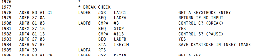
Memory location 135 (&H87 hex) contains the last key handled by INKEY$. Except, that must not be technically correct because it works without calling INKEY$. Looking further into the disassembly, I see that it is actually where the BREAK CHECK stores the key it found:

It checks for BREAK and also the PAUSE key (SHIFT+@ on the CoCo keyboard, which now I see returns as &H13 from the “GET A KEYSTROKE ENTRY” routine). Thus, while INKEY$ uses this location…

…it is not involved with setting that location. (Note to self: Explore what KEYIN does.)

Doing a PEEK(135) will return whatever the last pressed key was, as detected by the looping BREAK check code. By itself, you could use this for a game where the player never stops moving, or only stops when you press a “stop moving” key.

GAME: Never Stop Moving using PEEK

0 REM nsm.bas
10 CLS0
20 PRINT STRING$(32,153);
30 FOR A=0 TO 12
40 PRINT CHR$(153);STRING$(30,32);CHR$(153);
50 SOUND 200-A*2,1:NEXT
60 PRINT STRING$(32,153);
70 L=1024+8*32+16:SC=0
80 POKE L,255:SOUND1,1
90 K=PEEK(135)
100 IF K=94 THEN M=-32
110 IF K=10 THEN M=32
120 IF K=8 THEN M=-1
130 IF K=9 THEN M=1
140 POKE L,96:IF PEEK(L+M)=96 THEN L=L+M ELSE 200
150 PRINT @480,SC;:IF K<>0 THEN SC=SC+1
160 GOTO 80
200 SOUND 1,5
210 PRINT @32*7+11,"GAME OVER!";
999 GOTO 999

In this pointless game (though I’ve seen worse for smartphones), you begin moving a red block around the screen using the arrow keys. Once you start moving, it will never stop unless you crash into a wall, ending the game. How high of a score can you make?

GAME: Never Stop Moving using INKEY$

It would have been easier (and more portable) to do this without PEEK and use INKEY$. All we would have needed was a check for no key being pressed, and then continue using the last direction used. Something like this would work:

0 REM nsm2.bas
10 CLS0
20 PRINT STRING$(32,153);
30 FOR A=0 TO 12
40 PRINT CHR$(153);STRING$(30,32);CHR$(153);
50 SOUND 200-A*2,1:NEXT
60 PRINT STRING$(32,153);
70 L=1024+8*32+16:SC=0
80 POKE L,255:SOUND1,1
90 K$=INKEY$:IF K$<>"" THEN K=ASC(K$)
100 IF K=94 THEN M=-32
110 IF K=10 THEN M=32
120 IF K=8 THEN M=-1
130 IF K=9 THEN M=1
140 POKE L,96:IF PEEK(L+M)=96 THEN L=L+M ELSE 200
150 PRINT @480,SC;:IF K<>0 THEN SC=SC+1
160 GOTO 80
200 SOUND 1,5
210 PRINT @32*7+11,"GAME OVER!";
999 GOTO 999

By avoiding CoCo-specific PEEKs, this version may run on an MC-10 or Dragon.

But, using PEEK may be faster since it has less BASIC to churn through than an INKEY$, IF and ASC() conversion. (Note to self: Benchmark PEEK versus INKEY$, assuming I haven’t already done that in an earlier article.)

But what if you wanted the player to move ONLY when the key is being pressed down? INKEY$ cannot do that, and neither can PEEK(135). That’s where the second memory location come in to play:

Decoding the (keyboard) Matrix

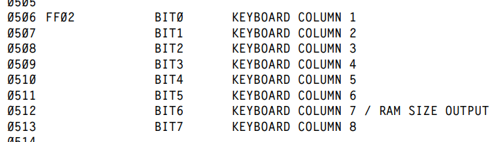
The Unraveled book shows that memory location 65282 (&HFF02) is part of a PIA that is hooked to the keyboard column matrix. BASIC uses this to determine which key is being held down:

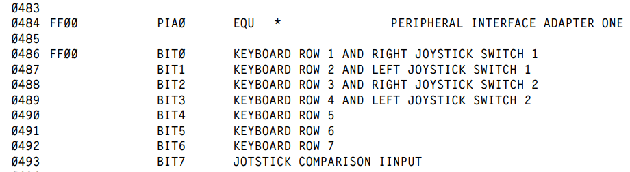
Two bytes earlier is a similar value for the keyboard rows:

These bits are set or clear based on what key in the keyboard matrix is being held down.

                Color Computer Keyboard Array 
    Pin 1 --- @ --- A --- B --- C --- D --- E --- F --- G 
              |     |     |     |     |     |     |     | 
    Pin 2 --- H --- I --- J --- K --- L --- M --- N --- O 
              |     |     |     |     |     |     |     | 
    Pin 3 nc  |     |     |     |     |     |     |     | 
              |     |     |     |     |     |     |     | 
    Pin 4 --- P --- Q --- R --- S --- T --- U --- V --- W 
              |     |     |     |     |     |     |     | 
    Pin 5 --- X --- Y --- Z -- UP -- DWN - LFT - RGT - SPACE 
              |     |     |     |     |     |     |     | 
    Pin 6 --- 0 -- 1! -- 2" -- 3# -- 4$ -- 5% -- 6& -- 7' 
              |     |     |     |     |     |     |     | 
    Pin 7 -- 8( -- 9) -- :* -- ;+ -- ,< -- -= -- .> -- /? 
              |     |     |     |     |     |     |     | 
    Pin 8 -- ENT - CLR - BRK - ALT - CTL - F1 -- F2 - SHIFT 
              |     |     |     |     |     |     |     | 
    Pin 9 -----     |     |     |     |     |     |     | 
                    |     |     |     |     |     |     | 
    Pin 10 ----------     |     |     |     |     |     | 
                          |     |     |     |     |     | 
    Pin 11 ----------------     |     |     |     |     | 
                                |     |     |     |     | 
    Pin 12 ----------------------     |     |     |     | 
                                      |     |     |     | 
    Pin 13 ----------------------------     |     |     | 
                                            |     |     | 
    Pin 14 ----------------------------------     |     | 
                                                  |     | 
    Pin 15 ----------------------------------------     | 
                                                        | 
    Pin 16 ---------------------------------------------- 

But, from my testing, just PEEKing these I/O values does not work, at least not on Color BASIC 1.1. (Keyboard scanning changed a bit in later version of the Color BASIC ROMs.) I am unfamiliar with using the PIA so there may be some other things that have to be done to set it up before you can read it. Still, just PEEKing doesn’t do it for me.

10 PRINT PEEK(65282):GOTO 10

I get 255s over and over, though sometimes it looks like it might be blipping to a different value. To catch the changes, I tried this:

10 P=PEEK(65282)
20 IF P<>LP THEN PRINT P:LP=P
30 GOTO 10

Jim says it is 0 if nothing is pressed, or 255 if any key is being held down. From looking at the matrix, even if this did work, it seems like it would only be 0 if nothing was held down in any column, and 255 if a key was held down in each column. Can this be correct?

So I ask the audience: Why does this work for Jim, but not in the Xroar emulator I am using?

Comments are apprecaited!

To be continued…

Color BASIC “DATA” quirk.

I was in the middle of writing more on my CoCo Base-64 encoding series and stumbled upon some weirdness with the DATA command. Consider this silly program:

0 REM baddata.bas
10 READ A$:IF A$="" THEN END
15 PRINT A$;:GOTO 10
20 DATA ":"
30 DATA HELLO
40 DATA ""

This will print:

:HELLO

I know I could just have done DATA “:HELLO” but stay with me on this..

If you try to combine lines like this:

0 REM baddata.bas
10 READ A$:IF A$="" THEN END
15 PRINT A$;:GOTO 10
20 DATA ":":DATA HELLO
40 DATA ""

…you get this:

Color BASIC DATA quirk.

When I get a moment, I’ll have to look at the ROM disassembly and see what is going on.

Until then…

Compressing BASIC DATA with Base-64 – part 3

See also: part 1, part 2, part 3 and part 4.

A Faster Base-64

I had planned to end this series with this third part, giving a simple way to turn 8-bit value DATA statements into Base-64 DATA statements. But smarter folks than I have looked at my previous work, so now my plans have changed. We will need an extra part or two… or three.

Today, let’s highlight some comments made to previous installments.

The always thought-provoking MiaM wrote:

I would had written out the 2 exponent values directly as 4, 16 and 64 rather than using INT(2^2).

The decdode-4-“chars”-to-3-bytes parts could use a modified base 64 thingy where you have the first 6 bits of three bytes in a row, and the fourth “char” contains the upper two bits for the previous three “chars”/bytes. Or the other way around, start with the “char” that contains the upper two bits for the following three chars and put that in a numerical variable. Then have a loop that runs three times. Each time first shift the “upper two bits” variable two steps left, i.e. multiply by 4, and then read a “char” and to that char OR the result of the “upper two bit” variable ANDed with 192 (=%110000).

That format would be incompatible with the standardized representation used by BASE 64, but it would indeed be a format with the same density and using the same characters.

Btw you could use the “BASE 90” as a way to slightly compress some data, by just having the values >63 represent two instances of the actual value minus 64. That might not save much, but perhaps worth investigating.

MiaM

Very good point! Eliminating “power of two” calculations and changing them to hard coded values should offer a noticeable speed increase. Pre-calculating values (i.e. writing 4 instead of 2^2) is a good way to save some time, and possibly space too (since “2^2” takes up more memory than “4”).

Normally I would go on a Benchmarking BASIC tangent, but I will save that for later.

I was more intrigued by the concept of making an easier to parse Base-64 format. Since the original goal of this article was to cram as much type-able DATA numbers as possible in to a BASIC program, there is nothing that says it needs to follow the standard Base-64 encoding format. Any format that gets more bits of data in to type-able DATA values would suffice.

This opens up an opportunity to tweak the encode/decode method to be easier to do in BASIC. Mia suggests something like this:

Instead of the standard Base-64 encoding of three 8-bit values into four 6-bit values:

+- Byte 1 --+- Byte 2 --+- Byte 3 --+
| 000000|00 | 0000|0000 | 00|000000 |
| \__A__/\___B___/ \___C___/ \_D__/

We could alter the encoding into a different version:

+- Byte 1 --+- Byte 2 --+- Byte 3 --+
| 00|000000 | 00|000000 | 00|000000 |
| \| \_A__/   \| \_B__/ | |/ \_C__/ |
|  \___________D__________/

The benefit here is that decoding this in BASIC could be done much easier and faster. Rather than all the multiplication/division needed to shift bits and then combine them into bytes, it could be as simple as this a few ANDs and divides. Here’s a rough example of converting three 8-bit (0-255) input values (A, B and C) into four 6-bit (0-63) output values (O1, O2, O3 and O4).

0 REM 6BIT.BAS
1 REM As proposed by MiaM

10 READ A,B,C
15 REM --XXXXXX of A
20 O1=(A AND &H3F)

25 REM --XXXXXX of B
30 O2=(B AND &H3F)

35 REM --XXXXXX of C
40 O3=(C AND &H3F)

45 REM XX------ of A
50 O4=(A AND &HC0)/4

55 REM XX------ of B
60 O4=O4+(B AND &HC0)/16

65 REM XX------ of C
70 O4=O4+(C AND &HC0)/64

75 PRINT "ENCODED:"
80 PRINT A;B;C,O1;O2;O3;O4

85 A=0:B=0:C=0
90 A=O1+INT(O4 AND &H30)*4
100 B=O2+INT(O4 AND &HC)*16
110 C=O3+INT(O4 AND &H3)*64

120 PRINT "DECODED:"
125 PRINT O1;O2;O3;O4,A;B;C

1000 DATA 111,222,123

Running this program displays:

Three 8-bit values converted to four 6-bit values, and back.

The three 8-bit input values (111, 222 and 123) are converted into four 6-bit output values, then those four are turned back into three 8-bit values to verify it worked.

The conversion is very simple, since the output values O1, O2 and O3 are just the right 6-bits of the input values A, B, and C, which can be obtained by using AND to mask off the top two bits:

20 O1=(A AND &H3F)
30 O2=(B AND &H3F)
40 O3=(C AND &H3F)

Optimization Note: We could save a few bytes by omitting the parenthesis and the space before the &H3F. Due to how the Color BASIC’s parser works, we need the space between the variables (A, B and C) and the keyword “AND”. That space is what tells the tokenizer we want a variable followed by the keyword AND, versus a variable that starts with “AA”:

A=255

PRINT A AND 4
4

PRINT A AND4
4

PRINT AAND4
0

Above, Color BASIC thinks the third example is a variable called “AAND4” which is truncated to just be “AA” since Color BASIC only cares about the first two characters of a variable name:

A=255
AAND4=42

PRINT AAND4
42

PRINT A AND4
4

Oh the fun bugs that must have caused me back in the day!

But I digress…

The fourth byte is built by doing the opposite AND to get only the top two bits of A, then a divided that by 4 to shift them to the right 2 bits (AA—— to —AA—-), then do the same mask to B and divide by 16 to shift them 4 bits to the right (BB—— to ——BB–) and again for C divided by 64 to shift 6 bits to the right (CC—— to ——CC) and then add them together to make the result (–AABBCC).

50 O4=(A AND &HC0)/4
60 O4=O4+(B AND &HC0)/16
70 O4=O4+(C AND &HC0)/64

I think I did a poor job explaining that. But here it is visually:

INPUT (three 8-bit values):

A: aaAAAAAA
B: bbBBBBBB
C: ccCCCCCC

OUTPUT (four 6-bit values):

O1: --AAAAAA
O2: --BBBBBB
O3: --CCCCCC
O4: --aabbcc

Maybe that helps.

Doing it this was can be done faster and with less code, I think. Some benchmarking needs to be done to see if AND is faster than addition for combining the values, and the O4 line can just be made as one thing without the intermediate line numbers and steps:

50 O4=(A AND &HC0)/4+(B AND &HC0)/16+(C AND &HC0)/64

We will want to make the decoder as small as possible, since if we save 100 bytes doing BASE-64 over HEX and the decoder takes more than 100 bytes it defeats the purpose.

Maybe we can figure out this “base 90” concept in a future article, as well.

To be continued…

Compressing BASIC DATA with Base-64 – part 2

See also: part 1, part 2, part 3 and part 4.

Today we will explore writing a standard base-64 converter in BASIC, and then see if we can make a smaller and faster (and nonstandard) Color-BASIC-specific one.

When we last left off, we were looking at ways to get as much encoded data on to a DATA statement as possible. Instead of using integer numbers (base-10) or hex values (base-16), we began exploring if we could increase the base and use more typeable character to encode the data.

Although it seems we could create a weird base-90 format using every typeable character except for quote (which we’d need to start a DATA line else we couldn’t use comma), the decoder would be much larger and have to do much more work, and we actually wouldn’t benefit since we really need numbers that round to specific numbers of bits:

  • Base-8 (octal) values can be represented by 3-bits (111). (Extended BASIC supports octal when you use &Oxx or just &xx.)
  • Base-16 (hexadecimal) values can be represented as 4-bits (1111). (Extended BASIC supports hexadecimal when you use &Hxx.)
  • Base-32 values would be represented as 5-bits (11111).
  • Base-64 values would be represented as 6-bits (111111).
  • Base-128 values would be represented as 7-bits (111111).

As you can see, a base-90 value isn’t a large enough range to give us an extra bit over base-64. We need to use bases that are nice multiples of the power of 2. Because of this, we’ll ignore a made-up base-90 and look at something a bit more standard, such as base-64 encoding.

Pump up the base

As previously discussed, natively, you can represent a number in a DATA statement as a base-10 value, or a hexadecimal value. Both of these are the value 32:

100 DATA 32,&H20

BASIC will READ them the same way, though hex values are much faster for BASIC to read and parse. Using native hex values like “&H20” is the fastest way to load DATA, but it is also the largest since every value has two extra characters (“&H”) in front.

A recent tip was given by Shaun Bebbington about how you can represent zero just by leaving it out between commas. It saves space, and the parse gets zero from this faster than if you put a zero there:

100 DATA 8,6,7,5,3,,9

But since we are trying to get as much DATA in there as possible, we don’t want to separate numbers by commas. We can pack all the 2-digit hex values together in a string then read that entire string and parse out the individual 2-digit hex values. That is more work, and slower, but gets more data per DATA line. Here are the values 0 to 15 in hex (00 to 0f):

100 DATA 000102030405060708090A0B0C0D0E0F

As previously demonstrated, this is the most efficient way to store HEX values. Even when we pad a low 0-15 value to make it two digits (1 represented by 01), it stills saves space over comma delimited values since no commas are used.

But each hex value is wasting 50% of the bits it takes to represent it. HEX values of 0-15 could be represented by four bits (0000 to 1111). We are storing them as one 8-bit character and thus achieving 50% storage efficiency.

We can do better by using a higher base-x value that can use those wasted bits. We want the highest value we can represent with typeable characters, which is 64 (since the next higher would be 128 and we don’t have a way to type 128 different characters on the CoCo).

Base-64

The standard Base-64 encoding uses the following 64 characters to represent values of 0 to 63:

ABCDEFGHIJKLMNOPQRSTUVWZYZabcdefghijklmnopqrstuvwxyz01234567890+/

Each base-64 character needs 6-bits to be represented (000000-111111).

Representing values that way only wastes 2 bits per character, rather than 4-bits like hex base-16 does:

ASCII HEX Chars.:    ASCII Base-64 Chars.:
      0    15              0    63
     "0"   "F"            "A"   "/"
     /       \            /       \
xxxx0000  xxxx1111   xx000000   xx111111

But, converting to and from base-64 is much trickier. Hex base-16 is as simple as this:

  • Hex F0” -> F is 15 which is 1111 in binary. 0 is 0000 in binary. Thus the first character becomes the left four bits, and the second character becomes the right four bits. Super easy. Barely an inconvenience. Two ASCII bytes represent one byte of data.

But for base-64, we are dealing with 6-bits, and two of those won’t fit into an 8-bit byte. Instead, four base-64 6-bit values are merged together to make a 3-byte 24-bit value.

  • Base-64 “ABCD” (xx000000 xx000001 xx000010 xx000011) -> A is 0 which is 000000 in binary. B is 1 which is 000001 in binary. C is 2 which is 000010 in binary. D is 3 which is 000011 in binary. These values are merged together (removing the unused 2-bits in each one) and stored in 3 bytes as:
+- Byte 1 --+- Byte 2 --+- Byte 3 --+
| 000000|00 | 0001|0000 | 10|000011 |
| \__A__/\___B___/ \___C___/ \_D__/
  • Byte 1 contains 6 bits of base-64 value A and 2 bits of base-64 value B.
  • Byte 2 contains 4 bits of base-64 value B and 4-bits of base-64 value C.
  • Byte 3 contains 2 bits of base-64 value C and 6 bits of base-64 value D.

Well that’s a mess. Moving bits around like that is super easy under languages like C, but a bit more work in BASIC.

Encode this!

We will start with encoding a simple ASCII string into base-64 using a web tool:

https://www.base64encode.org

If you go to that link, you can type something in and then encode it into base-64. I typed:

Greetings from Sub-Etha Software! Do you know where your towel is?

And that gets encoded into this:

R3JlZXRpbmdzIGZyb20gU3ViLUV0aGEgU29mdHdhcmUhIERvIHlvdSBrbm93IHdoZXJlIHlvdXIgdG93ZWwgaXM/

Each character represents a 6-bit (0-63) value which we will have to combine into 8-bit values and decode.

An easy way to decode the characters used by base-64 encoding is with a string:

10 Z$="ABCDEFGHIJKLMNOPQRSTUVWXYZabcdefghijklmnopqrstuvwxyz0123456789+/"

We can use Extended BASIC’s INSTR() function to match a character from the encoded string with a character in that string, and the position it is found in will the the value it represents (well, minus 1, since INSTR returns a base-1 value).

Here is an example that will display the bytes of the encoded string:

0 REM base64-1.bas
10 Z$="ABCDEFGHIJKLMNOPQRSTUVWXYZabcdefghijklmnopqrstuvwxyz0123456789+/"
20 READ A$:PRINT A$
30 FOR A=1 TO LEN(A$)
40 PRINT INSTR(Z$,MID$(A$,A,1))-1;
50 NEXT
1000 REM BASE-64 DATA
1010 DATA R3JlZXRpbmdzIGZyb20gU3ViLUV0aGEgU29mdHdhcmUhIERvIHlvdSBrbm93IHdoZXJlIHlvdXIgdG93ZWwgaXM/

Running that shows me this:

Displaying base-64 values.

If A is 0, then R should be 17, and that is what it prints first. Now we know we can get the values for each character in a base-64 encoded string.

Next we have to turn four 6-bit base-64 values into three bytes (24-bits). I am not sure what a good way to do this is, so I’ll just brute-force it and see how that works out.

First, I know that I need four base-64 values to make my 3 8-bit values, so I’ll modify my loop to skip every four values, and then add an inner loop to process the individual four base-64 values.

Inside that inner loop it will process the next four base-64 6-bit values and convert them into 3 8-bit values.

Here is what I came up with:

0 REM base64.bas
5 POKE65395,0
10 Z$="ABCDEFGHIJKLMNOPQRSTUVWXYZabcdefghijklmnopqrstuvwxyz0123456789+/"
20 READ A$
30 FOR A=1 TO LEN(A$) STEP 4
35 REM GET 4 6-BIT VALUES
40 FOR B=0 TO 3:B(B)=INSTR(Z$,MID$(A$,A+B,1))-1
50 IFB(B)<0 THEN B(B)=0
60 NEXT
65 REM CONVERT TO 3 8-BIT
70 C1=INT(B(0)*INT(2^2)) OR INT(B(1)/INT(2^4))
80 C2=(B(1) AND &HF)*INT(2^4) OR B(2)/INT(2^2)
90 C3=(B(2) AND &H3)*INT(2^6) OR B(3)
100 PRINT CHR$(C1);CHR$(C2);CHR$(C3);
110 NEXT
120 END
1000 REM BASE-64 DATA
1010 DATA R3JlZXRpbmdzIGZyb20gU3ViLUV0aGEgU29mdHdhcmUhIERvIHlvdSBrbm93IHdoZXJlIHlvdXIgdG93ZWwgaXM/

I figured out all the 6-bit to 8-bit stuff (lines 70-90) with alot of trial and error, so I expect there is a faster and easier way to do this. But, then end results is a program that will print out the expected message, albeit really slowly.

A successful, but slow, decode of a base-64 encoded message.

One unexpected problem was with the powers of two — (2^2) and such. They produce rounding errors which caused some bits to be lost. I had to use INT() round them. That took me hours to figure out, but it’s just part of the inaccuracies of floating point values, especially limited ones like a 1970s BASIC used.

PROBLEM: Since the goal here is to put more data in DATA statements, the base-64 decode routine needs to be small. If it is 100 bytes larger than just using HEX, you have to save 100 bytes in DATA before you break even. The routine I give is not small and not fast. It would probably not be useful in the 10 LINE contest I mentioned. Maybe one of you can help improve it.

Now that we have a simple base-64 decoder, the next step will be making an encoder to turn DATA statement values into a base-64 string.

Until next time…