
When I got my first Radio Shack TRS-80 Color Computer 1 back around 1983, I dove into the Getting Started manuals and learned all the new wonderful commands that EXTENDED COLOR BASIC offered me that my Commodore VIC-20 did not have. Commands like PLAY for music, SOUND for a beep, and graphics commands to draw CIRCLEs, LINEs and even DRAW complex objects were … amazing.
On my original tape based CoCo (EXTENDED COLOR BASIC) the high-resolution graphics memory started just after the memory used for the 32×16 text screen:
DEC     HEX     DESCRIPTION
-----   ----    -----------
0       0000    Color BASIC Use
512     0400    Text Screen
1536    0600    Hi-Rez Graphics
Knowing that, as I learned some 6809 assembly language I wrote routines to scroll a PMODE 4 256×192 graphics screen. I used this to do video titles for my dad. I’d create a screen using a graphics program, and load that into the second half of the graphics memory, then let my routine smooth scroll that screen into view.
I’d love to find that old source code and see how awfully inefficient it was. I bet one of you could really show me a faster way to do it.
But I digress…
DISK EXTENDED BASIC changed everything!
The next major leap in home computing for me was getting a disk drive for my CoCo. Imagine being able to store up to 156K of data on a floppy disk, and load things at such blazing speed (compared to the tape player and it’s 1500 baud rate).
It was nice… but it broke my assembly code! It turned out, when DISK BASIC was added, it used memory after the text screen for its own purposes, and shifted the high resolution graphics memory 2K further down in the memory map:
DEC     HEX     DESCRIPTION
-----   ----    -----------
0       0000    Color BASIC Use
512     0400    Text Screen
1536    0600    Disk BASIC Use
3584    0E00    Hi-Rez Graphics
Learning this, I adjusted my assembly routines to work on graphics screens starting at 3584 (disk systems) rather than 1536 (tape systems).
How do we know?
I wondered if there was some programmatic way to tell where the screen started. I don’t think this even dawned on me back in the 1980s, but I asked this question to the new Color Computer mailing list and quickly got an answer:
Word at $BC (GRPRAM) is start of graphics RAM. Word at $BA (BEGGRP) gets you the start of the current view window.
Juan Castro
Enviado do meu Olivetti Programma 101
http://retropolis.com.br
Bonus. Not only can you tell where graphics memory starts, but you can tell which page is displayed. With EXTENDED BASIC, you have 8 1.5K pages of graphics memory you can use. You reserve them with the PCLEAR command (it defaults to 4 pages). You can learn more about PCLEAR in this article.
PMODE 3 (128×192 4-color) and PMODE 4 (256×192 2-color) both need 4 pages, so you can have two screens in those modes. PMODE 0 uses 1 page, so you can have 8 pages in that ode.
- PMODE 0 – 128×96 2-color (1536 bytes)
- PMODE 1 – 128×96 4-color (3072 bytes)
- PMODE 2 – 128×192 2-color (3072 bytes)
- PMODE 3 – 128×192 4-color (6144 bytes)
- PMODE 4 – 256×192 2-color (6144 bytes)
When you use PMODE, the first parameter is the graphics mode, and the second is which page for the screen to start on. For PMODE 4 you can do “PMODE 4,1” to get one screen of 4 pages starting at page 1, and “PMODE 4,5” to get a second screen of 4 pages starting at page 5. You can set PMODE to the first screen and draw something, then set it to the second screen and draw something different, then flip back and forth between them using PMODE. Here is a silly example:
0 'GFXFLIP.BAS
10 PCLEAR 8
15 ' DRAW FIRST SCREEN
20 PMODE 4,1:PCLS:SCREEN 1,1
30 CIRCLE(128,96),50
35 ' DRAW SECOND SCREEN
40 PMODE 4,5:PCLS:SCREEN 1,1
50 LINE (10,10)-(245,171),PSET,B
60 ' FLIP THROUGH THEM
70 PMODE 4,1:SCREEN 1,1
80 FOR A=1 TO 100:NEXT
90 PMODE 4,5:SCREEN 1,1
100 FOR A=1 TO 100:NEXT
110 GOTO 70
That program will reserve all 8 pages, then set a PMODE 4 screen starting at page 1. It draws a circle on that page. Then it sets a PMODE 4 screen starting at page 5. It draws a box on that screen. After that it just toggles between showing PMODE 4 starting at page 1, then at page 5, and the image will flicker back and forth between the circle screen and the square screen.
With low-resolution PMODE 0, you can do 8 screens of animation this way.
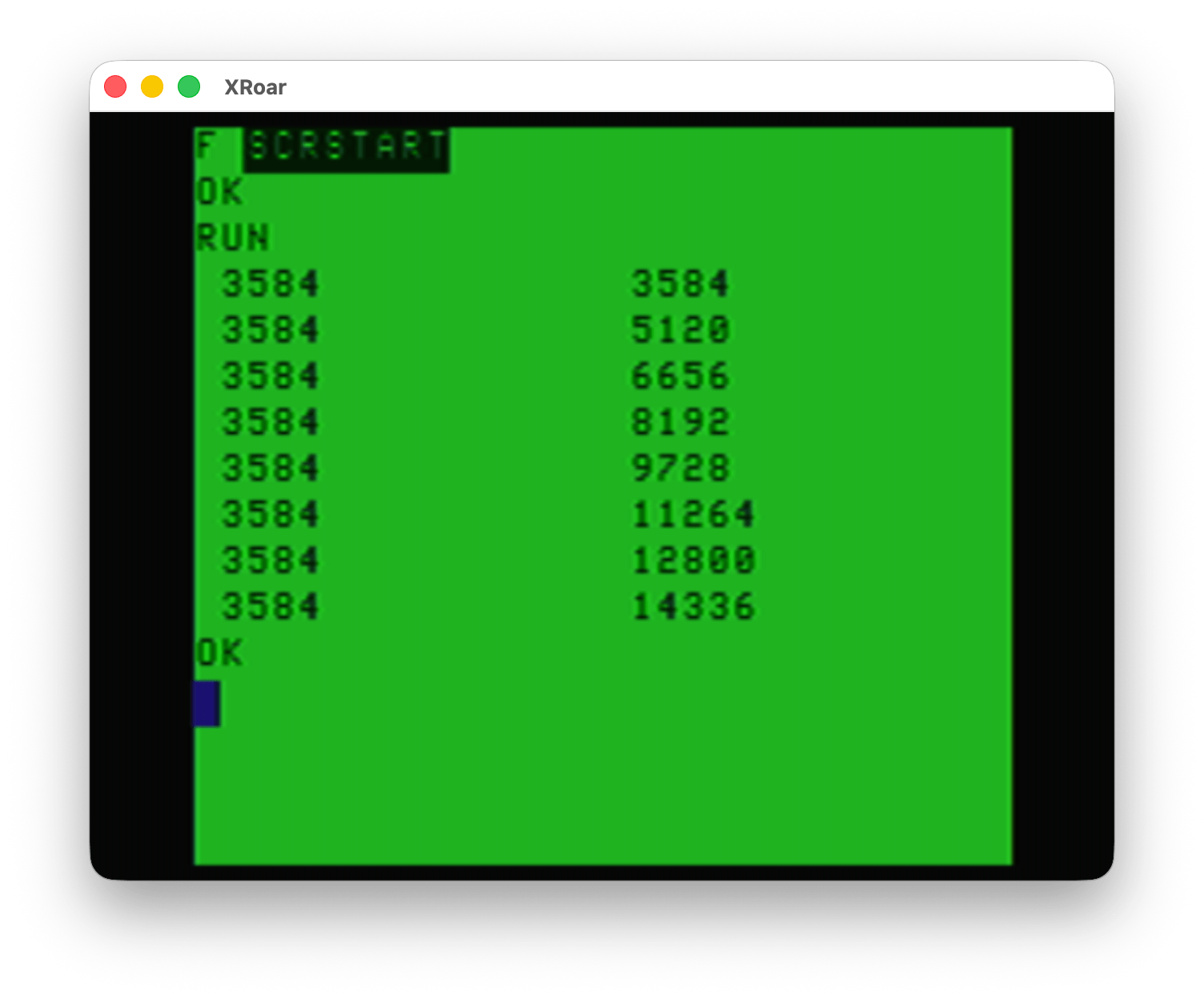
I wrote a second program that will print out where screen memory starts, and where the current viewed page starts.
0 ' SCRSTART.BAS
1 ' THANK YOU, JUAN CARLOS!
10 PCLEAR 8
20 FOR P=1 TO 8:PMODE 0,P
30 PRINT PEEK(&HBC)*256+PEEK(&HBD),PEEK(&HBA)*256+PEEK(&HBB)
40 NEXT P
When I run this on an tape-based EXTENDED BASIC CoCo (emulator) with no Disk Controller, it shows graphics memory starts at 1536 and then it toggles through each PMODE 0 page to show where each one would start:

And when DISK EXTENDED BASIC is used, the same program shows the memory locations starting 2K higher in memory:
Thank you, Juan Carlos, for telling me this. I wish I had known about this back then. I could have made my assembly program automatically find the start of the graphics screen rather than having to assembly separate versions for tape or disk systems.
Until next time…
Remember that in assembler you can use another graphic mode such as semi-graphics, try to do it so that it also works for them As additional information, some of these modes can be painted in one mode and then viewed in another mode. such as painting in mode 3 a circle and then seeing it in mode four or vice versa
The “draw in PMODE 3 then switch to PMODE 4” was a trick to use the red blue artifact color set, wasn’t it?
Where might I find what to do in assembly to try the SG modes? I have never done that!
yes correct that was used a lot to be able to easily use the artificial colors of mode 4
At the end of the manual that comes with the computer are all the graphic modes. It is also in the technical reference of the color computer. There is a green manual that will tell you the necessary addresses and the values that you must enter. If I remember correctly, there is sg4, 6, 8, 12 and 24.
https://colorcomputerarchive.com/repo/Documents/Manuals/Hardware/Color%20Computer%20Technical%20Reference%20Manual%20(Tandy).pdf
Goodness! I own this! I bought it for my CoCo 1. I don’t really know why. I didn’t understand it but there was something in it I needed to know.
I couldn’t put the direct link but you can find it in color computer archive and in archive org On page 8 there is some information and on page 24 also
From basic you can also place those semi-graphics, but every time you use any of the functions like cls or change some mode, you can return to a normal basic graphics mode.
semi-graphics are very interesting for making text adventures, including graphic text adventures
You can also fool extended BASIC into doing semi-graphics commands with SG12 or SG24, like GET, PUT, LINE with ,BF, etc. Nick and I did special CocoTech episode on that, and it eventually spawned Nick’s H.E.R.O. game, written totally in Extended BASIC.
Is this basically doing some POKEs to the VDG and then using the existing commands, that don’t care what kind of RAM they are copying?