2024-08-01 – Fernando T. in the comments noted that there are still missing features: “I can see no control of bracketing steps and number of shots for composing HDR Photo yet…” Let’s hope that, eventually, Insta360 can make the X4 do as much as its predecessor could do.
Finally! The GPS Remote and Apple Watch may be used to control the X4. Also support for streaming. We are now getting close to the standard features we were used to with the X3.
In 2023, Home Depot sold an animated Halloween prop called Lethal Lily Swamp Witch. This prop was unique in that it has a rather nicely animate head that could move its eyes, blink, and tilt the neck in various directions. This was done by having the prop controlled by servos. Lethal Lily is much more advanced that most props that just use simple motors and gears to repeat motions.
The animated head is controlled via a four-wire connector which provides power, ground, a serial data line, and some kind of line that pulses to control the servos. Somehow.
While I do not yet understand how the pulse line works, I have been able to capture the pulse timing from the Control Box with the goal of having the Arduino generate the same pulses directly to the head — hopefully animating it without using the Control Box.
Using my LethalLilyReader program from the previous part, I was able to capture the serial and pulse data and display it as numbers. This allowed me to copy the pulse timing data so I could put it in a new program that would pulse the blue wire going to the head on and off with appropriate timing delays between each change.
I will skip all the trial and error I went through to get this far, and just share the program.
One thing I should mention — since the Saleae was showing times like 145.6 ms and such, I wanted to capture the time as accurately as possible. I used micros() on the Arduino to capture microseconds. When I went to play this back, I saw that my delayMicroseconds() were not working. I found this note:
TCurrently, the largest value that will produce an accurate delay is 16383; larger values can produce an extremely short delay. This could change in future Arduino releases. For delays longer than a few thousand microseconds, you should use delay() instead.
Because of this, my choice was to use delay() and milliseconds (which might throw timing off, if those partial milliseconds matter — probably they don’t), or to use a combination of delay() for the large amount, then delayMicroseconds() for the remaining amount. Even then, this wouldn’t be 100% accurate since there is still the overhead of doing two library calls instead of just one.
ChatGPT provided me with this snippet:
void customDelayMicroseconds(unsigned long delayTimeMicros) {
    unsigned long delayTimeMillis = delayTimeMicros / 1000;
    unsigned long remainingMicros = delayTimeMicros % 1000;

    delay(delayTimeMillis); // This will not delay if delayTimeMillis is 0
    delayMicroseconds(remainingMicros); // This will handle the remaining microseconds
}
You will see this routine used in my program, below. Note that, since I am PRINTING OUT each pulse time (on, off, and time), it’s slowing it down anyway, so even with my “more accurate” delay, the timing will still be off from the Control Box. Hopefully this will not matter…
Here we go…
// LethalLilyWriter.ino
/*-----------------------------------------------------------------------------

 Lethal Lily Swamp Witch animatronic Control Box writer.
 By Allen C. Huffman (alsplace@pobox.com)
 www.subethasoftware.com

 This program writes the data to the Lethal Lily head over a
 serial and digital input.

 Hardware:

 https://sviservice.com/collections/2023/products/sv2323794

 Documentation:

 CONFIGURATION:
 1. Define the pins on the Arduino that will be used for TX in
 .  the Software Serial library (connected to the green wire), and the pulse
 .  sending pin (connected to the blue wire).

 VERSION HISTORY:
 2024-06-13 0.00 allenh - Created based on LethalLilyReader.ino
 2024-06-14 0.01 allenh - Changed to PIN 13 so onboard LED will blink.

 TODO:
 * TODO...

 TOFIX:
 * TODO...

 ---------------------------------------------------------------------------*/

/*--------------------------------------------------------------------------*/
// Configuration
/*--------------------------------------------------------------------------*/
#define BAUD_RATE       550
#define GREEN_WIRE_PIN  12  // Serial TX to HEAD
#define BLUE_WIRE_PIN   13   // Pulses OUT to HEAD

/*--------------------------------------------------------------------------*/
// Includes
/*--------------------------------------------------------------------------*/
#include <SoftwareSerial.h>

/*--------------------------------------------------------------------------*/
// RX pin connected to GREEN wire.
// TX pin not used.
/*--------------------------------------------------------------------------*/
SoftwareSerial mySerial(3, GREEN_WIRE_PIN); // RX, TX

/*--------------------------------------------------------------------------*/
// Globals
/*--------------------------------------------------------------------------*/
volatile unsigned int g_pulseCount = 0;

// Pattern one ON and OFF pulse time in micros.
const unsigned long g_pattern1[] = {
    108336,
    185892,
    161408,
    328592,
    200140,
    156160,
    191696,
    161860,
    222340,
    507668,
    63712,
    236864,
    481116,
    97364,
    77224,
    230036,
    189148,
    128228,
    219716,
    153316,
    144596,
    55636,
    66692,
    92192,
    99984,
    73600,
    158388,
    205228,
    244916,
    141988,
    97352,
    114224,
    194472,
    103252,
    239248,
    575908,
    459728,
    16744,
    64608,
    59992,
    64688,
    59916,
    65168,
    59624,
    64788,
    59820,
    67140,
    287636,
    400560,
    325912,
    225148,
    145256,
    80220,
    109232,
    278032,
    175556,
    253068,
    156324,
    174984,
    381868,
    333784,
    158776,
    108328,
    164388,
    108324,
    242136,
    297388,
    195164,
    155604,
    100400,
    269976,
    153988,
    211304,
    136536,
    175524,
    133576,
    147248,
    83664,
    91740,
    279872,
    381224,
    105904,
    83312,
    69700,
    119660,
    108528,
    216900,
    319000,
    139236,
    153120,
    69424,
    55812,
    114036,
    91828,
    127924,
    184272,
    216976,
    105800,
    133452,
    181064,
    139080,
    128108,
    69424,
    67880,
    122192,
    58644,
    74852,
    81140,
    77672,
    142156,
    60888,
    119856,
    61256,
    156028,
    77752,
    122588,
    63792,
    103344,
    102604,
    92016,
    91632,
    83948,
    94256,
    125492,
    75016,
    97204,
    111228,
    80860,
    155744
};


//Prototypes
uint8_t convertValue (unsigned int value);

/*--------------------------------------------------------------------------*/
// Setup
/*--------------------------------------------------------------------------*/
void setup() {
    // Arduino console port.
    Serial.begin(9600);
    while (!Serial);

    // Control Box serial baud rate.
    mySerial.begin(BAUD_RATE);

    pinMode(BLUE_WIRE_PIN, OUTPUT);

    for (int idx=0; idx<10; idx++) Serial.println();
    Serial.println("LethalLillyWriter - "__DATE__" "__TIME__);
}

/*--------------------------------------------------------------------------*/
// Main loop
/*--------------------------------------------------------------------------*/
void loop()
{
    Serial.println ("Sending pattern 1...");

    mySerial.write (convertValue (8)); // End any sequence.

    delay (1000);

    mySerial.write (convertValue (1)); // Sequence 1

    delay (745);

    for (int idx=0; idx < sizeof(g_pattern1)/sizeof(g_pattern1[0]); idx++)
    {
        if (idx & 1)
        {
            digitalWrite(BLUE_WIRE_PIN, HIGH);
            Serial.print ("On for ");
        }
        else
        {
            digitalWrite(BLUE_WIRE_PIN, LOW);
            Serial.print ("Off for ");
        }
        Serial.println (g_pattern1[idx]);

        // Large values do not work for delayMicroseconds(), so a custom
        // function is used to delay using ms, then leftover time in us.
        customDelayMicroseconds (g_pattern1[idx]);
    }

    Serial.println ("Done.");

    while (1);
} // end of loop()


/*--------------------------------------------------------------------------*/
// Convert number (1-8) to Lethal Lilly byte format (0011 1100).
/*--------------------------------------------------------------------------*/
uint8_t convertValue (unsigned int value)
{
    uint8_t returnByte = 0;

    if ((value < 1) || (value > 8))
    {
        Serial.println ("convertValue must be 1-7 (pattern) or 8 (end).");
        returnByte = 0;
    }
    else
    {
        returnByte = value | (~value << 4);
    }

    return returnByte;
}

// Created by ChatGPT.
void customDelayMicroseconds(unsigned long delayTimeMicros) {
    unsigned long delayTimeMillis = delayTimeMicros / 1000;
    unsigned long remainingMicros = delayTimeMicros % 1000;

    delay(delayTimeMillis); // This will not delay if delayTimeMillis is 0
    delayMicroseconds(remainingMicros); // This will handle the remaining microseconds
}

// End of LethalLilyWriter.ino
This program will send serial data out at 550 baud on Arduino pin 12 (which will hook to the green wire going in to the head), and pulse data on pin 13 (which will go to the blue wire in to the head). I chose pin 13 for the pulse line because it also has an LED connected to it on the UNO, and this will blink in time with the pulses being sent to the head.
The Arduino I/O pins are only 5V, while the Control Box pulses at 5.4V. I expect this may cause some differences in what the Arduino sends versus what the Control Box sends. Let’s find out!
Arduino, meet Lethal Lily’s head
I used the Control Box to provide power to the head via the red and black wires. I also connected the black ground wire to the Arduino, giving everything a common ground (bad things happen if you don’t do this, as I found out years ago when dealing with programmable LED strips using external power supplies).
My wiring looked like this:
Control Box  Head         Arduino UNO
-----------  -----------  -----------
Green        Green--------PIN 12
Red----------Red
Black--------Black--------GND
Blue         Blue---------PIN 13 (build in LED)
My hope was that the Control Box could act as a power supply, providing 5.9V DC to the head, then the Arduino could act as the Control Box sending serial data on pin 12 to the head’s green wire, and pulsing data on pin 13 to the head’s blue wire.
My program sends the byte code for pattern 1, pauses (using the delay I could see from the Saleae Logic Analyer), then starts sending ON and OFF pulses using the time values I captured in the LethalLilyReader program. When the last pulse is sent, I do a short delay and then send out the “end” byte.
When I went to test it, it actually did something! The head does indeed animate, but the mouth did not move at all. Perhaps the low 5V power of the Arduino UNO’s I/O pin is not enough to match what the head expects. The Control Box sends pulses at 5.4V and perhaps at a much higher amperage than the Arduino is capable of.
This was an exciting first step.
Some questions…
Why does the mouth not work? Is this due to the Arduino only able to pulse at 5V instead of 5.4V like the Control Box?
What do the pulses actually mean? How can we control the servos in the head to create custom animations?
Some answers…
I tried writing a test program to send pulses at different rates, but nothing happened. It does look like the blue wire expects something beyond a digital I/O signal. I decided to take a chance and see what happens if I route power (from the Control Box red wire) in to the blue wire. I tapped a wire between the two, quickly, and saw … the mouth opened!
It looks like the blue wire has nothing to do with the servos at all! It just controls the mouth. The pulses I was capturing are only the mouth movements, to align with the audio being played by the Control Box! All the motion in the head (eyes, eyelids, neck) was just being done by the head itself when it receives the start code byte!
To test this, I made a simple program that would send the start byte code… and the head began animating. The pulses had nothing to do with the head animation (other than the mouth).
I guess I should have started there!
The bad news…
The bad news is that it looks like we cannot control the servos in the head, as-is. If we were hoping to make the animatronic look in specific directions or blink at specific times … that is not possible. While it may be possible to hack the head and get access to all the wires running to the servo, that was not I was hoping for. Also, since the blue wire needs a signal with more power than what the Arduino I/O pin can provide, there will be some extra hardware (like a relay) needed to control the mouth.
The good news…
The good news is — now we don’t have to learn how to control all those servos! The head will just “do its thing” and we can control the mouth to match custom audio. This is probably good enough for most things — an animated prop that delivers a custom spiel.
To test this, I took the power out from the Control Box (red/black wires) and ran them throuh an Arduino Relay Shield that then connected to the head’s blue/black wires. This would allow me to pulse the 5.9V coming out of the Control Box power supply to the head’s blue wire.
And it worked!
Here is the first simple test I did, where I played some audio and manually toggled the relay (that is the clicking sound you will hear) to make the mouth open/close — like a puppet :)
Lethal Lily Swamp With as … the Ghost Host.
At this point, I believe I understand what I need to do to. By using a cheap triggered MP3 player (either an Arduino Shield, or some external board), and a relay, it should be quite easy to make Lily “speak” any audio I want her to.
My electronics (MP3 players, etc.) are in storage currently, so I am not sure how soon I can get to it, but I hope that this series will be…
So far, I have figured out that the Lethal Lily Control Box sends out serial bytes at around 550 baud (on the green wire), with a byte sent at the start of a sequence, and a different byte sent at the end.
In between these two serial bytes, a second (blue) wire is pulsing at different rates. This looks like PWM pulses to control the position of servos. (Me from the future: It is not…) The question is … how does one stream of dozens of pulses end up at the different servos in the head? (Me from the future: It does not…)
To figure that out, it’s time to experiment — and hopefully not destroy the servos in the head at the process! (Many devices have no protection so you can tell the servo to go so far it breaks the mechanism. Without knowing how the internals of the head operate, I risk ruining this thing if I send it the wrong kind of pulse.)
Instead of just trying to send pulses and see what happens, I decided I might like to capture the pulses that come from the Control Box, and try to recreate them on the Arduino and see if I get the same result.
5.9V Warning
The power supply used by the Control Board is 5.9V. The Arduino UNO I/O pins are 5V pins, so connecting higher voltage to them may cause damage. I decided to enable the Analog channel in my Saleae Logic Analyzer capture and see what voltage is coming out of the blue wire.
This tells me that the pulses are 5.4V — a bit lower than the 5.9V power supply, but still beyond the voltage that should go in to an I/O pin.
I consulted ChatGPT to ask how I could drop the voltage down to sub-5V for the Arduino.
I know these A.I. tools can spew bad information, but if this is correct, I should be able to use two resistors and drop the power down to a safe level for the Arduino to read.
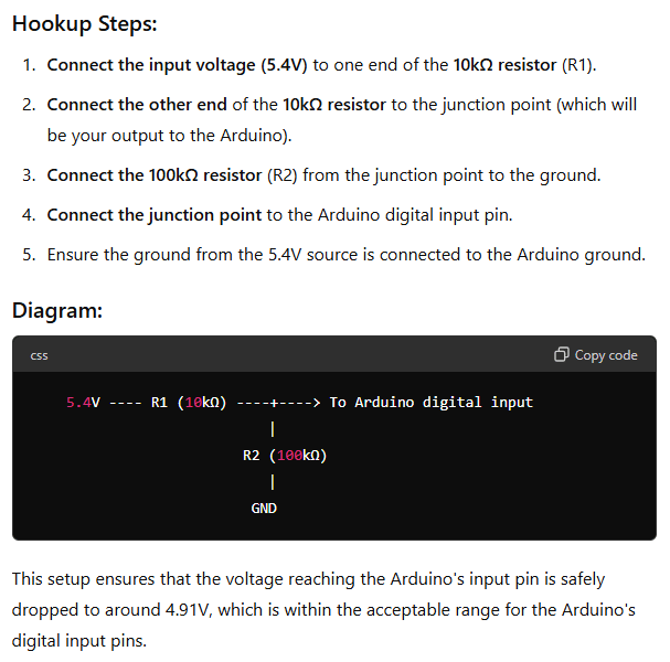
Here is a rough look at how I tried to wire that up.
Arduino voltage divider to take 5.4V down to below 5V.
Hardware folks, quit laughing. This is complicated for a software guy ;-)
I use PIN 2 for reasons I will explain in just a moment.
I did skip some of the steps it took me to get here. Initially, ChatGPT gave me different resistor values. I did not have resistors of the proper values available, and since Radio Shack doesn’t exist anymore, I asked if there were ways to do it with other values. It made a table for me, and I was able to use two resistors I had on-hand. The A.I. was quite helpful in showing options until I got one that worked for what I had.
Counting Pulses
By asking ChatGPT, I was able to make some super simple code that could count how many pulses were coming from the Control Box. But, I wanted to do more than that. I wanted to know how long each pulse was on, and off in between. To do this, I needed to record the time when the pulse changed state (off to on, or on to off) and then later I could do math on those values to figure out how long each pulse was on or off.
If my program were doing nothing but this, I might be able to brute-force it by just reading the pin in a loop. If it changed state (low to high, or high to low), get the current time. If there was a previous time (previous change), print how long it’s been since the last change.
#define BLUE_WIRE_PIN   2   // Pulses IN

void setup() {
    Serial.begin(9600);
    while (!Serial);

    pinMode(BLUE_WIRE_PIN, INPUT);

    Serial.println ("Running...");
}

void loop() {
  unsigned long time = 0;
  static unsigned long s_prevTime = 0;

  int pinStatus = 0;
  static int s_lastPinStatus = -1;

  pinStatus = digitalRead (BLUE_WIRE_PIN);

  if (pinStatus != s_lastPinStatus)
  {
    // Pin changed. Record the time.
    time = millis();

    if (s_prevTime != 0)
    {
      // Print how much time since last change.
      Serial.println (time - s_prevTime);
    }

    s_prevTime = time;
    s_lastPinStatus = pinStatus;
  }
}
When I run this, then trigger the device, I see a series of numbers print out representing the pulse (on or off) times.
I found that if you switch the Control Box to “OFF – TRY ME” and then back to “SENSOR“, it will reset to pattern 1. I did this so I could capture the pulses for pattern 1.
But, when I compare these times with the times of the pulses seen by the Saleae, they are very different. For example, the first on pulse reported by the Arduino script is 108 ms, but the Saleae thinks it is 145ms.
This is caused by the pulse signal having some decay after it turns “off”. Rather than being a sharp ON/OFF square pulse, it stays on, then slopes down at the end. The Saleae detects the “end” at a different point in this slope than the Arduino does.
You can see there is about a 35ms delay from the time the signal starts sloping off until the Saleae sees it as “off”. The Arduino sees “off” pretty much right when the signal starts to drop. (108 ms detected by Arduino plus 35 ms is 143 ms, very close to what the Arduino is calculating). I suspect if this is important to the head, we can easily compensate in software by adding to the values the Arduino calculates.
But we’re not there yet.
Suffice it to say, it does seem easy to capture the pulses and record how long each is, which would allow us to play them back to the head later, with the Arduino generating the same pulse sequence that the Control Box did.
Using Arduino Interrupts
When I first did this test, I thought the reason I was getting different numbers was caused by the code doing other things before it got back to check the pin. The pin cand change while the code was elsewhere in the loop, and by the time we get back to read the pin, it’s a bit later than when the change actually occurred.
To compensate for this, I learned how to use Arduino Interrupts. Some pins can generate an interrupt when they change, and you can configure Arduino to run a routine any time this change happens. On the Arduino UNO, only pins 2 and 3 can generate interrupts. This is why I chose PIN 2 for my example.
I updated my example to use an interrupt service routine (ISR) instead of manually polling the pin:
#define BLUE_WIRE_PIN   2   // Pulses IN

void setup() {
    Serial.begin(9600);
    while (!Serial);

    pinMode(BLUE_WIRE_PIN, INPUT);

    attachInterrupt(digitalPinToInterrupt(BLUE_WIRE_PIN), pinChangedISR, CHANGE);

    Serial.println ("Running...");
}

void loop() {
}

// This will be called any time the pin changes state.
void pinChangedISR()
{
    unsigned long time = 0;
    static unsigned long s_prevTime = 0;

    // Pin changed. Record the time.
    time = millis();

    if (s_prevTime != 0)
    {
      // Print how much time since last change.
      Serial.println (time - s_prevTime);
    }

    s_prevTime = time;
}
In this version, the main loop() is now empty. All the work is being done inside the ISR. This is normally not how you would use an interrupt since, while processing the code inside the ISR, any more interrupts may be missed. The ISR code needs to be as small and quick as possible. It works for this example because the timing of the pulses is quite slow (pulses lasting many milliseconds) but this is still not a good example of an ISR.
When I run this, I see similar numbers. This tells me the difference in Arduino vs Saleae values was not the code being too slow. I also saw some 0 values. This told me the Arduino might be seeing glitches on the line that were not full pulses. Some “debounce” code could be added to fix this, but that’s outside the scope of this quick test.
During this test, I also learned that the millis() (millisecond time) counter on the UNO incrementis at a value of 1.2 each time, then would jump ahead every so often to catch up. This might explain some of the drift in numbers I see when re-running this. To make the timing more accurate, I will switch to using micros() (microseconds) which will be as precise of timing available on the Arduino. More on that later…
Now that I have a basic understanding of how I can read the green wire serial data, and the blue wire pulse data, I came up with a test program that displays both. Here is my LethalLilyReader test program that displays the serial bytes, then the pulse information, for each pattern as it is triggered. The pulse data is collected in the ISR, but not printed until the pattern is done, which makes the interrupt service routine smaller and faster.
I also made it count the number of pulses and display that, so I could further compare what the Arduino sees to the Saleae.
And as a final feature, I fudge the timing numbers to compensate for the sloping voltage delay the Control Box sends at the end of a pulse. This is not perfect, but it gets the numbers pretty close to how Saleae sees them.
Here is the full program (but check my Github for any changes since this article was posted):
// LethalLilyReader.ino
/*-----------------------------------------------------------------------------

 Lethal Lily Swamp Witch animatronic Control Box reader.
 By Allen C. Huffman (alsplace@pobox.com)
 www.subethasoftware.com

 This program reads the data come from the Lethal Lily Control Box over a
 serial and digital input.

 Hardware:

 https://sviservice.com/collections/2023/products/sv2323794

 Documentation:

 CONFIGURATION:
 1. Define the pins on the Arduino that will be used for RX in
 .  the Software Serial library (connected to the green wire), and the pulse
 .  counting pin (connected to the blue wire with 10K/100K resistors to drop
 .  the voltage from 5.4V down to below 5V).

 VERSION HISTORY:
 2024-06-12 0.00 allenh - Created basic serial (green wire) reader.
 2014-06-13 0.01 allenh - Adding pulse (blue wire) support.

 TODO:
 * Capture data and then playback to the head.

 TOFIX:
 * TODO...

 EXAMPLE OUTPUT:

[0xE1 - 11100001] PLAYING #1 ... [0x78 - 1111000] STOPPED.
Pulses: 65
[0xD2 - 11010010] PLAYING #2 ... [0x78 - 1111000] STOPPED.
Pulses: 71
[0xC3 - 11000011] PLAYING #3 ... [0x78 - 1111000] STOPPED.
Pulses: 59
[0xB4 - 10110100] PLAYING #4 ... [0x78 - 1111000] STOPPED.
Pulses: 68
[0xA5 - 10100101] PLAYING #5 ... [0x78 - 1111000] STOPPED.
Pulses: 75
[0x96 - 10010110] PLAYING #6 ... [0x78 - 1111000] STOPPED.
Pulses: 74
[0x87 - 10000111] PLAYING #7 ... [0x78 - 1111000] STOPPED.
Pulses: 57
[0xE1 - 11100001] PLAYING #1 ... [0x78 - 1111000] STOPPED.
Pulses: 65
----------------------------------------------------------------------------*/

/*--------------------------------------------------------------------------*/
// Configuration
/*--------------------------------------------------------------------------*/
#define BAUD_RATE       550
#define GREEN_WIRE_PIN  12  // Serial RX
#define BLUE_WIRE_PIN   2   // Pulses IN

/*--------------------------------------------------------------------------*/
// Includes
/*--------------------------------------------------------------------------*/
#include <SoftwareSerial.h>

/*--------------------------------------------------------------------------*/
// RX pin connected to GREEN wire.
// TX pin not used.
/*--------------------------------------------------------------------------*/
SoftwareSerial mySerial(GREEN_WIRE_PIN, 3); // RX, TX

/*--------------------------------------------------------------------------*/
// Globals
/*--------------------------------------------------------------------------*/
volatile unsigned int g_pulseCount = 0;
volatile unsigned long g_pulseTime[200] = { 0 };

/*--------------------------------------------------------------------------*/
// Setup
/*--------------------------------------------------------------------------*/
void setup() {
    // Arduino console port.
    Serial.begin(9600);
    while (!Serial);

    // Control Box serial baud rate.
    mySerial.begin(BAUD_RATE);

    pinMode(BLUE_WIRE_PIN, INPUT);
    attachInterrupt(digitalPinToInterrupt(BLUE_WIRE_PIN), countPulseISR, CHANGE);

    for (int idx=0; idx<10; idx++) Serial.println();
    Serial.println("LethalLillyReader - "__DATE__" "__TIME__);
}

/*--------------------------------------------------------------------------*/
// Main loop
/*--------------------------------------------------------------------------*/
void loop()
{
    static bool isPlaying = false;
    unsigned char ch;

    while (mySerial.available())
    {
        // Read byte from Control Box.
        ch = mySerial.read();

        // Display byte received as hex and binary.
        Serial.print ("[0x");
        Serial.print (ch, HEX);
        Serial.print (" - ");
        Serial.print (ch, BIN);
        Serial.print ("] ");

        // Byte will have the sequence number (1-7) as the right four bits,
        // and the inverse of those bits as the left four bits. At the end
        // of the sequence, a value of 8 is sent the same way.
        //
        //              Hex Binary
        //              --  ---- ----
        // Sequence 1 - E1  1110 0001 (1)
        // Sequence 2 - D2  1101 0010 (2)
        // Sequence 3 - C3  1100 0011 (3)
        // Sequence 4 - B4  1011 0100 (4)
        // Sequence 5 - A5  1010 0101 (5)
        // Sequence 6 - 96  1001 0110 (6)
        // Sequence 7 - E1  1000 0111 (7)
        // End of Seq - 78  0001 1000 (8)

        // Validate. Left nibble AND with right nibble should be zero.
        if ( ((ch & 0xf0 >> 8) & (ch & 0x0f)) != 0)
        {
            // If not, bad byte received.
            Serial.println ("INVALID.");
        }
        else // Good byte received.
        {
            // Check for end of sequence (8).
            if ((ch & 0x0f) == 8)
            {
                Serial.println ("STOPPED.");

                if (isPlaying == true)
                {
                    Serial.print ("Pulses: ");
                    Serial.println (g_pulseCount);

                    isPlaying = false;

                    // Calculate pulse durations.
                    calculatePulseDurations ();
                }
            }
            else
            {
                g_pulseCount = 0;

                Serial.print ("PLAYING #");
                Serial.print (ch & 0x0f);
                Serial.print (" ... ");

                isPlaying = true;
            }
        }
    } // end of while (mySerial.available())
} // end of loop()


/*--------------------------------------------------------------------------*/
// Calculate duration of each pulse.
/*--------------------------------------------------------------------------*/
// NOTE: The pulse times do not shut off immediately. There is about a 34ms
// decay time at the end of each pulse, which makes the Arduino values be
// much shorter than what the Saleae is seeing. I currently do not know how
// this impacts the signal seen by the head, but I will do some testing.
// Adding 37ms to the Arduino calculated "on" time, and subtracting 35ms
// from the "off" time, makes the values much closer.
void calculatePulseDurations ()
{
    for (int idx=0; idx<g_pulseCount-1; idx++)
    {
        unsigned long pulseTime = (g_pulseTime[idx+1] - g_pulseTime[idx]);

        //Serial.print ("(");
        //Serial.print (pulseTime);
        //Serial.print (")");

        // Fudge factors to make it match the values that the Saleae
        // logic analyzer calculates.
        if (idx & 1) // Off time
        {
            pulseTime = pulseTime - 35000; // 35.46206 average
        }
        else // On time
        {
            pulseTime = pulseTime + 37000; // 37.0141 average
        }
        //Serial.print ((float)pulseTime/1000); // millis
        Serial.print (pulseTime); // micros
        Serial.print (",");
    }
    Serial.println ();
}


/*--------------------------------------------------------------------------*/
// Pulse counter ISR.
/*--------------------------------------------------------------------------*/
void countPulseISR()
{
    // Store micros time when the pulse changed.
    if (g_pulseCount < (sizeof(g_pulseTime)/sizeof(g_pulseTime[0])))
    {
        g_pulseTime[g_pulseCount] = micros();

        g_pulseCount++;
    }
}

// End of LethalLilyReader.ino
Now that I can capture the serial and pulse data, I should be able to recreate it in the Arduino and write it out to the head, eliminating the Control Box (though without sound, since the Ardunio has no sound hardware).