This one even uses my customized version of Bo Zimmerman’s Zimodem ESP8266 Firmware.
https://www.simulant.uk/shop/retro-vintage-computer-wifi-modem-rs232-serial-hayes-compatible

This one even uses my customized version of Bo Zimmerman’s Zimodem ESP8266 Firmware.
https://www.simulant.uk/shop/retro-vintage-computer-wifi-modem-rs232-serial-hayes-compatible
Thanks to Rob Inman for sharing this link over on Discord. They have an RS-232 to WiFi module available, based on the ESP8266 module. They chose to include my pre-configured fork of Bo Zimmerman’s ZiModem (with the settings for standard RS232 rather than Commodore serial). Cool.
https://www.simulant.uk/shop/retro-vintage-computer-wifi-modem-rs232-serial-hayes-compatible

Updates:
Yesterday I updated my fork of Bo Zimmerman’s ZiModem. My custom fork is 100% his code, with only some configurations changed to make it default to standard RS-232 signals instead of inverted like the Commodore uses. (Basically, it’s what his “Guru modem” firmware defaults to, and the over-the-air update changed to point to builds on my service. Guru modem only builds for ESP32, so eventually I just need to figure out how to modify the project so it builds Guru modem for ESP8266, I think.)
NOTE: I only built for the NodeMCU-12E ESP8266 module and the generic ESP8266 (whatever that is) module. I did not have ESP32 libraries installed so there is no build for that currently.
If you want to pull the source code and build it directly through the Arduino IDE, you can find my fork here:
https://github.com/allenhuffman/Zimodem
The binaries I built are located here:
http://subethasoftware.com/files/zimodem/
I also wrote up some instructions for updating that firmware from a PC, Mac or Linux machine without having to build it with the Arduino IDE. (I had to use these steps myself, since I couldn’t remember how it worked.)
NOTE: If you have the ESP8266 wired up to a TTL-to-RS232 adapter, you may find that firmware updates will not work. On my device (using the full-signal TTL adapter and a NodeMCU ESP8266), I had to unplug the 3.3V power wire that goes from ESP8266 pin to the TTL-to-RS232 board. That was enough to make firmware updates work. I’m still not sure why having the TTL adapter hooked up affects loading firmware over USB, but apparently it does.
A final option is to use the ZiModem built-in over-the-air update capability, which we haven’t gotten to test yet since this is the first time I’ve updated firmware for the CoCoWiFi fork. That is done through the command:
AT&U
That should grab the latest build on my server. I believe it reads a .txt file from my server to get the version number and builds the filename out of that, then downloads that filename. You can also specify the version manually. Currently, there is a 3.4 build and a 3.5 build available on my site.
AT&U=3.5
Please let me know if this works for you. You should see the startup banner (1200 baud) show 3.5:

Original instructions on this WiFi modem for $10 can be found here:
Good luck!
Updates:
This is a fairly detailed guide to configuring a cheap ESP8266 WiFI module to act as a WiFi modem, then wiring it up to any computer with a traditional RS-232 port.
It can be as simple as hooking up four wires, or many more wires, or even making a breadboard prototype:


Currently, we have to download and build the special Zimodem firmware, but as soon as I figure out what it takes just to load a pre-built binary, this section will be removed.
The ESP8266 is a tiny WiFi device that can also run custom code. The development module version has a built-in USB-Serial adapter that can be used for debugging and loading firmware, and also gives a convenient way to power the module.
You will need a standard USB to microUSB cable to hook the ESP to a computer so you can load the firmware. Most Android phones use this type of cable, as do things like the Raspberry Pi. If you don’t have one, you can probably buy one at the local gas station.
This cable will also provide power for the ESP module, so it will need to be hooked to a computer’s USB port, or into a USB power supply like a phone charger. Again, commonly available even at the local gas station.
The ones I found have a standard DB9 female connector and contain circuitry that will convert the 3.3V chip-level TTL signals used by the ESP chip to standard 12V RS-232 levels that a computer uses. These will often will come with a short 4-wire jumper cable that can be used to hook them up to the ESP module.


Most of the RS-232 to TTL adapters I have seen come with a set of jumper wires with female ends. They slide over the pins on the board, and then slide over the pins of whatever you are connecting it to. They allow hooking up parts without needing soldering skills or even a breadboard. I find bundles of 40 of these for under $3.

Optionally, if you want something that is a bit more “stable” (without exposed pins and such), you can use a breadboard and male-to-male jumper wires, then plug everything up and jumper them together.
You will need a cable to go from your computer’s RS-232 port to the adapter. Your cable will depend on the type of RS-232 to TTL adapter you have. All the ones I have use DB-9 female connectors, but there are some that use a male connector.
For example, my Radio Shack Color Computer has a 4-pin DIN connector for the built-in Serial I/O port. Back then, cables where made that had a male 4-pin DIN connector on one end (to plug into the CoCo) and a male DB-25 connector on the other (to plug into a modem). If I could find my old cables, I could use them, but I would still need a DB-25 to DB-9 adapter to go between that cable and the smaller DB-9 connector of the RS-232 to TTL adapter.
Another common type of serial cable is a NULL modem cable, which was used to hook two computers together by serial ports. I have a NULL modem cable that has the male 4-PIN DIN connector on one end and a female DB-9 on the other. Since it is a NULL modem cable, it has the TX and RX lines swapped so it can plug directly to a “modern” PC’s serial port DB-9 male connector. To use this cable, I needed a male DB-9 to male DB-9 NULL modem adapter, which will swap the TX and RX again, making it a normal cable like the RS-232 to TTL adapter requires, and change the gender so it will plug into the TTL adapter.
I also have the Deluxe RS-232 Program Pak, which provides a full RS-232 port with a female DB-25 connector. To use that, I ordered a standard male DB-25 to male DB-9 cable from Amazon. This will plug directly from my RS-232 Pak to the RS-232 to TTL adapter.
Basically, you will need whatever serial cable your system requires and a way to convert it to plug into a DB-9 connector.
The ESP modules have their own software installed, and it includes a command mode where you can use “AT” commands (similar to the old Hayes Smartmodem standard) to do various WiFi things. But, this is not setup to emulate an old modem connection. Instead, we will use Bo Zimmerman’s excellent replacement firmware called Zimodem. He provides the source code, but you will have to download and build it, then load it into your module.
I am now maintaining a special version of Zimodem that has things set up for normal RS-232 use. (By default, the original Zimodem works in a Commodore mode for 8266, and normal for ESP32. My version works in normal mode for both.)
Most of the low-cost ESP parts use serial hardware that is not recognized by a Mac or PC (not sure about Linux). If you plug up your ESP part to your computer and it is not recognized as a serial port (Like COM5: on windows, or /dev/cu.SLAB_USBtoUART on Mac), you will need drivers.
Most sellers will provide links to where to find drivers. For the Amazon parts I purchased, they used the CP2012 chipset, and I had to download and install the drivers for it. Once installed, you can plug the ESP module up and it should show up as a new serial port device.
Because of the various methods available to install ESP firmware, I have split them out into a separate article.
Please read this article for details on how to load the firmware onto the module without needing to install the Arduino IDE, download the sources, and build it yourself.
Once the firmware has been installed on the module, you can open up the Serial Monitor in the Arduino IDE and verify it is running. You will need to set it to 1200 baud to match the default speed used by Zimodem, and have it set to “Carriage return“. You can type “AT” and it should respond with “OK”. You can type “AT+CONFIG” and it should startup the configuration process.

If you get this far, you are ready to hook it up to the RS-232 to TTL adapter and then connect it to your computer.
For simple serial ports, all you may need to do is hook up TX (transmit), RX (receive), VCC (3.3v) and GND (ground) between the ESP module and the TTL adapter. Here is the pinout of the NodeMCU ESP8266-12E module:

All you have to do is connect the jumper wires between the pins of this module, and the matching pins on the TTL adapter. Some TTL adapters may have TX and RX reversed, but in general you want to hook up like this:
3-wire hookup:

    TTL         ESP8266
    ===         ==================
2   RX  <------ TX  GPIO1 (TX)
3   TX  ------> RX  GPIO3 (RX)
5   GND <------ GND GND
    VCC <------ 3V3 3.3V
For one of my adapters, I found it would not work using the 3.3V pin, and I had to switch to using the Vin (voltage input) pin, which would be the 5V coming off the USB connection. *THIS IS NOT RIGHT since the I/O pins of the ESP modules are mean to handle 3.3V and not 5V, so use caution. If you absolutely can’t get it to work on 3.3V, you can do what I did, but you risk frying the ESP.* I have other adapters that work properly at 3.3V.
It looks like this (note I am using the incorrect Vin instead of VCC):
WARNING! Keep all the bare metal pins from touching anything else! They could cause a short if they made contact with any metal. To reduce the chance of this happening, I used some of the non-conductive packing foam that the ESP module came in, and plugged the exposed pins into it:

There are still a few exposed pins, and on the top side of the module are lots of metal parts and solder connections, so just make sure you keep away from any metal parts!
Now I was able to hook this up to my Color Computer’s Serial I/O port and load up an old terminal program and start using Zimodem.

A quick tidbit on RS-232…
There are nine lines used for RS-232. They go between the computer (DTE, data terminal equipment) to the device (DCE, data communication equipment). Prepare for many acronyms!
TX and RX: You can think of most lines as one-way paths, with some lines going from the computer to the device, and others going from the device to the computer. For instance, transmit (TX) from the computer goes one way to receive (RX) of the device. On the device, it’s transmit goes one way to the receive of the computer.
CTS and RTS: Some lines are used for flow control. Each device has a request to send (RTS) output line that goes to the other side’s clear to send (CTS) input line. CTS goes to RTS, and RTS goes to CTS, similar to have TX and RX and handled. For example, the computer turns on RTS (request to send) to tell the remote device it is okay to send data. The remote device reads this on it’s CTS (clear to send) pin. The reverse is also true, with the remote device’s RTS going to the computer’s CTS. Thus, if using flow control, the computer or device only send when their CTS (clear to send) line is active.
DCD: The device may also use carrier detect (DCD). For a telephone modem, when a call is connected, the device will turn on carrier detect. The computer can read the status of the DCD line to know if a connection is in progress.
RI: There is a ring indicator (RI) that was used by modems to indicate an incoming call. I’ve never used this at all, since the RS-232 interface I had back then wasn’t even wired for it.
DTR and DSR: I am less clear on how all these could be used, but in general, DTR was set by the computer to tell the remote device if it should hangup or not. The computer would “drop DTR” and that would force the modem to hangup. DSR is set by the device to indicate it is there and ready.
Here is a quick chart to explain them, specifically as how they are used by Zimodem:
 DTE (Comp.)        DCE (Modem)
 DB-9 Male          DB-9 Female
=============      =============
pin in    out      in    out pin
1   DCD <--------------- DCD   1
2   RX  <--------------- TX    2
3         TX  ---> RX          3
4         DTR ---> DTR         4
5   GND                  GND   5
6   DSR <--------------- DSR   6
7         RTS ---> CTS         7
8   CTS <--------------- RTS   8
9   RI  <--------------- RI    9
Some RS-232 interfaces require more than just TX and RX to be happy. The Color Computer’s RS-232 Pak, for example, uses a 6551 UART chip. This chip will not receive data unless it sees carrier detect (DCD). Old telephone modems would provide this DCD signal when a call was in progress, and drop the signal when the call ended This gave the computer a way to know if a connection was established or not. Unfortunately, this signal is not present in a 3-wire connection.
It was possible to hook two computers together without a modem by using a NULL modem cable. These cables would swap TX and RX, so one computer’s transmit would end up at the other computer’s receive. They would also often do some trickery to force the DCD signal to be active. They did this by tying some of the pins on the RS-232 port together:

If we really don’t care about this missing lines (like CTS/RTS flow control, DTR/DSR, etc.), we can modify the RS-232 to TTL adapter so make it provide a fake DCD signal back to the computer.
Using the above diagram as a reference, I was able to solder a few pins together and use a short piece of wire to recreate it on real hardware:

This modification makes it so anytime the computer enables DTR, it will make DCD and DSR read as if they are enabled. It is creating a fake status by looping the DTR signal back into the DCD and DSR input pins.
Since this 3-wire hookup also does not have CTS and RTS, if the computer is expecting CTS (clear to send) to be active, that can never happen and thus it can never send. This modification ties the outgoing RTS (request to send) back to the incoming CTS (clear to send). When the computer enables request to send, to tell the remote device it is okay to send, it will read that same signal as if the remote device sent in it’s own request to send (coming in on the CTS line of the computer).
So much stuff.
Suffice it to say, but tying these lines together, it will fool the RS-232 device into thinking there is an active carrier detect and data terminal ready signal from the demote device anytime DTR is enabled. And, it will see a clear to send signal anytime it turns on read to send… Loopy goodness!
With that said, if you don’t want to solder, you could pick up these RS-232 jumper devices and create the connection this way. Note that in this example, I do not have CTS and RTS tied together. For my specific test, I did not need it, but other RS-232 interfaces may require it.

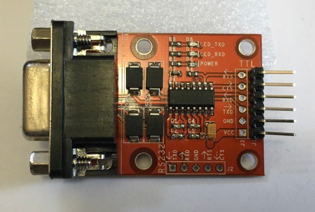
Another option is to use an RS-232 to TTL adapter that actually provides more of these signals. For a bit more, you can find an adapter that has CTS and RTS as well:
By adding two more wires between Zimodem and the adapter, you can use real hardware flow control. Zimodem will only send when it sees a clear to send signal from the computer, and if Zimodem can’t handle all the data it is receiving, it will disable it’s request to send, so the computer’s CTS line indicates “stop sending me stuff!”
    TTL         ESP8266
    ===         ==================
2   RX  <------ TX  GPIO1 (TX)
3   TX  ------> RX  GPIO3 (RX)
5   GND <------ GND GND
7   RTS ------> D1  GPIO5  (CTS)
8   CTS <------ D2  GPIO4  (RTS)
    VCC <------ 3V3 3.3V
This configuration still would not work for my 6551-based RS-232 Pak. I would still need to fake the carrier detect.
The final, and best, solution is to use an RS-232 to TTL adapter that actually provides all the signals that Zimodem supports and that your RS-232 interface may require. This requires hooking up even more wires (ten total):
    TTL         ESP8266
    ===         ==================
1   DCD <------ D4  GPIO2 (DCD)
2   RX  <------ TX  GPIO1 (TX)
3   TX  ------> RX  GPIO3 (RX)
4   DTR ------> D6  GPIO12 (DTR)
5   GND <------ GND GND
6   DSR <------ D7  GPIO13 (DSR)
7   RTS ------> D1  GPIO5  (CTS)
8   CTS <------ D2  GPIO4  (RTS)
9   RI  <------ D5  GPIO14 (RI)
    VCC <------ 3V3 3.3V
Mine looks like this:
If all those wires get to you, you can also do the same thing on a breadboard:
Although the wiring seems complete, there is one final issue that needs to be solved.
Zimodem, when built for the ESP8266, inverts all the RS-232 signals. This is because that is how Commodore computers did it, and Zimodem was designed for Commodore users. Commodore inverts HIGH and LOW from the standard, so all signals have to be inverted in
Zimodem from their defaults. On Commodore, “HIGH” means active. For RS-232, “LOW” means
active.
What this means is even if you have the carrier detect wired up properly, Zimodem is going to send the opposite signal. When a connection is in progress, the signal will read as “no carrier” to a normal RS-232 interface. When Zimodem is ready to receive data, the request to send will look like the opposite.
This causes huge issues :)
If you are using my special build of Zimodem, you can skip this section. I already pre-configure my version as follows.
Fortunately, Zimodem is fully configurable. Using simple “AT” commands, you can change the behavior of any of the incoming or outgoing RS-232 signals that Zimodem uses. All you have to do is be able to send some commands and then save the Zimodem configuration. Here is the summary:
AT S Settings:
==============
0=HIGH is active (defualt).
1=LOW is active.
2=force HIGH
3=force LOW

Sig  SReg Default RS-232 Standard
===  ===  ======= =================
DCD  S46  0       1 (force LOW)
CTS  S48  0       1 (force LOW)
RTS  S50  0       1 (LOW is active)
RI   S52  0       1 (LOW is active)
DTR  S54  0       1 (LOW is active)
DSR  S56  0       1 (LOW is active)
You can set these commands one at a time, like:
ATS46=1
OK
ATS48=1
OK
...etc...
…but you may find that the moment you toggle one of them, you appear to be locked out. This is because the inverted defaults actually work to our advantage. On my interface, I need DCD before I can receive. Zimodem has no carrier, so it is sending out the inverted “there is no carrier” signal, which reads as “carrier detect” for me. The moment I “fix” that so it sends the normal signal, I suddenly have no carrier and can no longer receive data.
You may choose to send all the commands in one line:
ATS46=1S48=1S50=1S52=1S54=1S56=1
However, as soon as that is done, you may not see “OK”. Carrier detect is still flipped… You may be able to still send commands, but you would be typing blind if your interface requires DCD before it will receive. Because of this, I like to force DCD to be always on:
ATS46=3S48=1S50=1S52=1S54=1S56=1
That command flips everything, but makes sure DCD (S46) is forced low (3), so it appears like a carrier is always present. This lets me communicate with Zimodem at all times.
If I were running a BBS that relied on detecting carrier, I would have to leave that at S46=1 and just send commands blindly. (BUT, one of my old terminal programs, Greg-E-Term, is not coded in a way that makes this work. It seems if there is no DCD, it doesn’t let me send anything at all. Other terminal programs I have do not behave this way, so I consider it an issue with what GETerm was designed to do.)
With all of this said, there are probably still many omissions. A future article needs to be a summary of useful Zimodem commands and tutorials on how to use it.
I also want to cover another alternate approach to having to configure with all those ATS commands. In my case, I simple modified the source code so the version I built had them setup the normal way so I never had to do any configuration.
And I need to document how to just install a binary without using Arduino IDE.
Until then… Comments greatly appreciated.
If you are using a NodeMCU-32S module like the one I ordered from Amazon:
HiLetgo ESP-WROOM-32 ESP32 ESP-32S Development Board 2.4GHz Dual-Mode WiFi + Bluetooth Dual Cores Microcontroller Processor Integrated with Antenna RF AMP Filter AP STA for Arduino IDE https://www.amazon.com/…/B…/ref=cm_sw_r_cp_tai_X5iFAbW6CD3ZJ
…you may want todo a few tweaks to the ZIMODEM. ZIMODEM is setup to build for Tools->Board->NodeMCU-32S.
There are two major differences in building Zimodem for the ESP8266 and the ESP-32:
//#define debugPrintf Serial.printf
#define debugPrintf doNothing
That will make it use the ESP32 code, and disable debug output.
//static HardwareSerial HWSerial(2);
#define HWSerial Serial
That will make the HWSerial port be the same one used by the USB console.
There is probably a better way, but this was the first time I got it going.
After that, the build you make will be controllable via USB port or the RS-232 port.
Things have been real busy lately at Sub-Etha Galactic Headquarters… Here are some updates:
The CoCoWiFi has been tested on the bitbanger serial port and things seem to work just fine.
On the RS-232 Pak, a modification was needed to make the pak actually receive data (forcing the carrier detect signal). This has been done by an easy soldering mod to the DB9 connector. The downside is that it does not provide true CD, and there is no support for hardware flow control or DTR to drop calls. For just a bit more, there are RS232-to-TTL adapters that provide hardware flow control, which might help for doing high speed transfers. However, the lack of carrier detect and DTR means they won’t work with a BBS like they should
Thanks to David Chesek, new RS232-to-TTL adapters were located that include all the signals. These would be the best choice for running with an RS-232 Pak. I have two different types of adapters, but have only done some initial testing. I was unsuccessful getting the first adapter to work. I plan to test the second version this week.
I hope to have a hardware announcement to make before the CoCoFEST!
I learned much while working on CoCoWiFi, so I returned to work on the previously “announced” SirSound project. I got everything wired up properly and was able to write a BASIC program to make it play tones. I also worked with John Strong and migrated the prototype over to an Arduino Nano (matching the original Arduino sound player board he sent me last year).
The next phases is to figure out the various modes that sound module will run in. I have proposed:
More to come…
I just wanted to pass along something I learned about last year. There is an inexpensive chip that handles USB host operations, allowing you to plug in devices like keyboards, mice, joysticks, etc. The chip is about $4 in quantities of one, and much cheaper if you order in bulk.
I found a company in the UK that uses this chip on a small circuit board that lets you plug in a USB device, and then get output via serial commands. You can hook this up to an Arduino and read a modern keyboard or mouse, for example. They have various firmware loads you can put on it to handle different protocols.
Just passing it along… I will have more to say on this soon.
Updates:
If you want to get your Tandy / Radio Shack Color Computer (CoCo) on the internet (or any other 80s computer with a serial port), here is a dirt cheap way you can do it.
Just a few years ago, adding WiFi to an Arduino meant buying a $60 add-on. My solution at the time was to get a much cheaper Ethernet and then use a cheap TP-LINK WiFi router hooked to it. I later found a source for a $10 Ethernet shield that made the overall cost even lower.
In 2014, the internet lit up with the discovery of the ESP8266 – a complete “WiFi on a chip” solution for under $5! Initially, all documentation was in Chinese but folks managed to figure out how to use it and, as they say, the rest is history.
Today the ESP8266 family of products is used in all kinds of things. There are now internet-enabled light switches, and front-ends for 3-D printers, and many other devices that get online thanks to this low-cost solution.
And, this includes all these retro computing platforms!
If you want to experiment, you can order an ESP8266 development board from Amazon for $8.79. This contains the low-cost ESP8266 module and then runs out all the various connection to pins, and also has a USB-Serial adapter built in. This USB port allows you to plug it up to a Mac or PC and upload new firmware, or use the device directly through a serial connection.
Here is the module I purchased. You can find many variations, some costing more, and others costing less. I wanted one I could get direct from Amazon using 2-day Prime delivery, but if you don’t mind waiting, you can find a similar part shipped from China for about $4.

Since my 1980s computers do not have a USB port, I needed a way to hook them up to the old-style RS232 serial port instead. For that, I bought a cheap RS232-to-TTL adapter. Here is the one I purchased for around $7, shipped from Amazon with 2-day Prime shipping. I see there are some for a few bucks less which might work just as well, and if you don’t mind waiting a few weeks to get something shipped from China, I have seen them for about .67 cents!

Now all I had to do was connect the two modules together using some jumper wires. I needed four wires to connect Voltage (mine needed 5v), Ground, Transmit and Receive. You can buy a bundle of these wires for just a few dollars.
Once connected, it looked like this:

I can power the module using a standard micro USB cable and charger (just like you might already have for an Android phone or Raspberry Pi or some models of Arduinos).
After this, all I needed was a NULL Modem cable to connect that DB9 connector to the Serial I/O port of my Color Computer. In my case, I used a “Driverwire cable” which has a 4-pin DIN connector on one end and a DB9 on the other. I needed to use a NULL Modem adapter to get the signals talking.

The final step I needed to do was to install different firmware on the ESP8266. The firmware that comes on the module does allow you to type certain “AT” commands and connect to WiFi and remote systems, but I wanted something easier and more compatible. I found this ZIMODEM firmware:
This makes the ESP8266 look like an old-style Hayes Smartmodem. Instead of using commands to dial a phone number, the commands will “dial” a remote telnet BBS. i.e., instead of:
ATDT 515-555-1212
…you can dial a telnet connection:
ATDT "coffeemud.net:23"
There are new commands added to display all nearby WiFi base stations, and connect to them. There’s even a command to retrieve a file from a web server! You can find full documentation on the ZIMODEM website.
Any terminal program can be used to make these types of connections. You can also configure it to receive incoming connections, and when someone telnets to your IP address, you will see a “RING” (just like the smartmodems did) and can have the system answer. Yep, it would be very easy to put an old-school BBS on the internet with this!
I was able to use this to connect an old Radio Shack CoCo to a remote BBS using the Greg-E-Term terminal program over the bitbanger port at 1200 baud (oooh, speedy).
I got these steps from the Amazon page for the ESP8266 part I purchased. I have edited them with additional notes and links.
Instruction & Steps of How to use:
UPDATE: I did not need step 4 when I recreated these steps on my Mac, so maybe they are not even needed on the PC side these days.
These steps worked for me, but I want to go back through them (as well as finding Mac instructions and Linux if someone can assist me with that) and add photos and more details.
ZIMODEM was created for Commodore computers, and has some special features in it for translating normal ASCII to Commodore’s PETASCII. It also comes with steps on how to use it with a Commodore from BASIC (with some assembly language routines used for high-speed reading and writing to the modem – sound familiar?). They have source code for various internet utilities such as:
With DriveWire on the CoCo, some of this exists but only for OS-9. It is my hope that we can easily port these BASIC programs (and even replicate the assembly language routines) over to the CoCo and do the same thing.
More to come…

NOTE: This is a work-in-progress. Check back for updates. I will note any revisions at the top of this article.
Updates:
In July 2015, Roger Taylor began the process of recreating a CoCo 3 system in an FPGA (field programmable gate array). Using a low-cost (less than $80) Terasic DE0-Nano development board and a custom I/O add-on board, he quickly got a virtual CoCo running. He has been continually improving the system and adding more features. His “CoCo on a Chip” Facebook group has documented this every step of the way.
Last year, I had acquired one of these DE0-Nano development boards and the RGB22VGA add-on board from Ed Snider. I was planning on using it to hook my old CoCo 3 up to a borrowed VGA monitor. But, at last year’s 25th annual CoCoFEST! near Chicago, Mark Marlette of Cloud-9 was selling his all-in-one version of this RGB to VGA adapter. I picked on of those up, and never used the DE0-Nano.
Roger recently sent me one of his add-on boards so I can finally put together my own FPGA CoCo. Let’s see how it goes…

Roger’s add-on board has RAM, two PS/2 style ports, a 1/8″ audio output jack, and VGA port. There are header connectors for plugging in a module that handles the SD card, and ones for WiFi and Bluetooth. My unit has The SD card and WiFi installed. I will be ordering a Bluetooth module for wireless serial ports (they are very cheap).
The card has writing along the bottom indicating which direction it should be plugged up tot he DE0-Nano: “Faces DE0-Nano USB connector –>>”:

You can also tell orientation by the cutout in the board, which lines up with some small 2-pin connector on the DE0-Nano below:

It seems the first step will be to install the Terasic software, and then hook the DE0-Nano up and load Roger’s firmware. The software is only available for Windows and Linux. Since I am a Mac user, I will either have to run it via virtualization (I use Parallels Desktop and Windows 10) or find a PC to use. I have several Raspberry Pis running Linux, so maybe that is an option as well.
After that, you will have to install a driver, and lastly you will be able to load Roger’s firmware on to the device and turn it in to an FPGA CoCo. Here are the steps I took:
Download it here:
I am using the Windows version, so my screen shots will be from that version.

This will make available a program called “Quartus II 12.1 Programmer” in the Altera 12.1 Build 177 folder.
NOTE: Your version number may be different if you are using later or earlier versions than I have. If you are setting up one of these, I’m sure you can figure that out.
When you plug in the DE0-Nano to the computer, Windows should prompt you for a driver. My Windows 10 did not, so I had to manually install it. If yours does, you can skip the next step and go straight to how to browse to the driver.
First, I had to open the Device Manager and find the USB-Blaster in the Other devices section:

Double clicking on USB-Blaster brings up information about the device:

Select “Update Driver…” and then choose “Browse my computer for driver software“. You have to manually tell it where the driver will be found (inside the programmer install directory):

On my system, I used the default install location and the driver was located here:
C:\altera\12.1\qprogrammer\drivers\usb-blaster\


Your directory names may be different, depending on what version of the software you install. Browser there, and then click Next:
The system should find the driver and install it.
Plug in the DE0-Nano to a USB port using the included cable, then launch the Quartus II 12.1 Programmer application.

If your Hardware Setup box says “No Hardware”, click the Hardware Setup button and select “USB-Blaster“:

After you close that windows, you can use File->Open to browse to and load the FPGA firmware image you downloaded from Roger’s Facebook page:

When it is loaded, you will need to check off “Program/Configure” and (probably optional) “Verify” to enable the Start button:

Once those two buttons are checked, you can then click Start to begin programming. After a few moments, you should see “100% (Successful)” in the top right green box:

Congratulations! You now have an FPGA CoCo!
After these steps, I plugged the device up to a VGA monitor and plugged in my PS/2 keyboard to the left port, and powered it up. It should instantly come to life with a familiar green screen, but if you have not prepared the special SD card for it yet, it will hang, trying to boot from that card.
You can hold down ESCape when you power up to bypass that, and find yourself at a nice virtual CoCo:

In the next part, I will figure out how to configure the SD card so I can actually load some software on it, and save any programs I create.
Until then … wow. This was easy! I can’t wait to see what all it can do. Thanks, Roger!

Now working without the crystal. This is using a Teensy and one of the pins to generate a 4mhz signal. I will post a video in coming days, hopefully, as soon as I have some CoCo BASIC code talking to it.
The green and black wires running off of it wold go to a headphone jack that the cassette cable could plug in to so you could feed Sound back to the CoCo without needing to use an external speaker. AUDIO ON!