
In part 1, I rambled on a bit about my experience with external hard drives and I stated that next I would explain “why I chose Drobo” and that we’d “look at the 2nd generation model versus the 3rd generation model.”
I guess I should do that.
Never Enough Storage
“Just buy a larger hard drive,” people tell me. It must be nice to have so little content you want to store that you can just buy an extra drive and be done with it. As an early adopter of digital photography (I got my first digital camera in 1996), I have taken several hundred thousand digital photos over the years. With no negatives, keeping those digital originals safe is very important. I learned this the hard way when I had a hard drive failure and lost a year’s worth of photos. The only copies I had were the scaled-down and watermarked versions on my website. At least I had those!
All my earlier photos had been archived to stacks of CD-Rs, so I was able to recover most of them, but it was clear I would have to make backups more regularly just in case it ever happened again. (“Just buy more DVD-Rs”.)
And it happened again. Several times, actually. I’ve had a number of hard drives fail on me unexpectedly. Most were still “new” drives, well under warranty. While Seagate or Western Digital will promptly replace the drive, that does little for you data. ALWAYS MAKE BACKUPS! (And always check reviews. The “more reliable” hard drive brand to buy has changed a number of times of the years. I am currently using Western Digital drives, but many years ago I wouldn’t have touched a WD for anything important.)
CD-Rs Aren’t Backups
For me, my main backup strategy was making sure all my digital photos and digital video files were archived to CD-R (then, later, DVD-R). I have stacks of these discs, but, sadly, some of my earliest CD-R backups no longer read. That’s right, Virginia. CD-Rs are not “forever” media. Exposure to UV rays in light can cause bit rot. Just because you copy something to a plastic disc doesn’t mean it’s safe long term.
When I learned CD-Rs were not enough, I decided I needed to do a combination of things:
- Every bit of important data should be archived to CD/DVD. Even if it’s not necessarily a long term solution, it’s still important to have a backup that can’t be taken out by a power surge or by dropping a computer.
- Every bit of important data should exist on at least two hard drives.
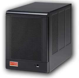
qBox 4-drive enclosure (photo from their website).
I started using some qBox-F quad-drive enclosures on my Mac. I had two of them – one for primary storage and the other for backup. Each one was “JBOD” (just a bunch of disks) so they appeared are four separate drives to my Mac. Soon, though, four drives was not enough and I needed more storage. Every time I did, I had to get out the screwdriver and swap out drives and spend hours copying data back and forth. There had to be a better way.
A Better Way: Trayless Hard Drive Enclosures

iStarUSA v7AGE220-SAU enclosure (photo from their website)
The next thing I found were trayless hard drive enclosures. They let you slide bare drives in and out without using tools. I bought a few inexpensive iStarUSA brand 2-drive enclosures. (I always like to have two matching enclosures in case one of them dies so I can swap drives out and get to my data in an emergency.) I was using the now-discontinued Firewire version for primary store (faster than USB 2.0) and had a cheaper USB-only version for emergency backup.
I also found a company that sold plastic hard drive cases that looked like old VHS rental tape cases. I ended up with a bookshelf full of hard drives. When I would copy data to one of them, I would also copy it to the second backup hard drive.
This worked quite well, but every time my collection grew I had to buy two more hard drives (primary and backup). I was hoping for a way to save some money while still getting protection. That’s what let me to research RAID-type hard drive systems.
Saving Money by Going RAID
With RAID, multiple drives are used and data is spread across all the drives. Every block of data is duplicated on another drive. If one drive fails, any data on that drive still exists somewhere else in the RAID array. This sounded like a good solution, but RAID has some limitations.
RAID systems want all drives to be of matching size (and preferably, type). If you put in a 500GB drive and a 750GB drive, the RAID would only use the largest amount that is common to all drives (in this case, 500GB – thus wasting the rest of the 750GB drive). You were also locked to that size. If a drive failed and you replaced it with a larger drive, the data would rebuild on the new drive, but it would only use the size of the former drive. Thus, you couldn’t upgrade capacity without starting over with an all new set of larger drives and copying everything over.

My 2nd generation Drobo (currently for sale on e-Bay).
I ended up going with a Drobo because their non-standard “magic” was that you didn’t have to have matching hard drives. You could start with two drives of any size, and then add more (up to four) to expand. When you started running out of space, you could replace a drive with a larger one and continue to do this as needed. Drobo looked like a great solution to my ever-growing need for backup data.
Up next: Drobo pros and Drobo cons.


